WATER PUMP INSTALLATION

-
INSTALL WATER PUMP ASSEMBLY
-
Install a new gasket, the water pump and tension spring bracket with the 6 bolts.
- Torque:
- 23 N*m { 230 kgf*cm, 17 ft.*lbf }
-
-
INSTALL TIMING BELT
- SST
- 09960-10010 ( 09962-01000, 09963-01000 )
-
SET NO.1 CYLINDER TO TDC/COMPRESSION
-
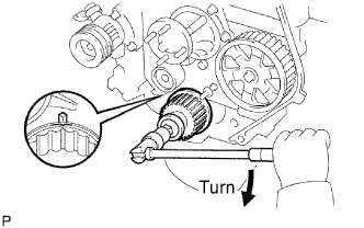
Using the crankshaft pulley bolt, align its groove with the timing pointer by turning the crankshaft clockwise.
Note
Do not turn the crankshaft pulley counterclockwise.
-
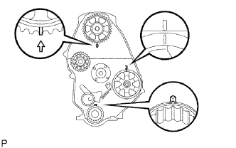
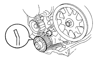
Set the timing and drive pulleys at each position.
Note
-
The engine should be cold.
-
When turning the crankshaft or camshaft, the valve heads will hit against the piston top. Do not turn them more than necessary.
-
-
-
INSTALL TIMING BELT GUIDE
-
Install the belt guide with the cup side facing outward.
-
-
INSTALL TIMING CHAIN OR BELT COVER SUB-ASSEMBLY
-
Remove the 2 nuts and wire harness clamp bracket.
-
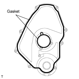
Install the 2 gaskets to the timing belt cover.
-
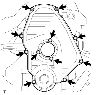
Install the timing belt cover with the 11 bolts.
- Torque:
- 11 N*m { 105 kgf*cm, 8 ft.*lbf }
-
Install the 2 nuts and wire harness clamp bracket.
-
-
INSTALL CRANKSHAFT PULLEY
- SST
- 09213-54015 ( 91651-60855 )
- 09330-00021
-
INSTALL VANE PUMP PULLEY
-
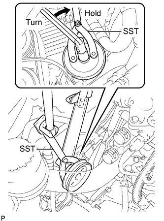
Using SST, install the vane pump pulley to the vane pump assembly.
- SST
- 09960-10010 ( 09962-01000, 09963-01000 )
- Torque:
- 43 N*m { 439 kgf*cm, 32 ft.*lbf }
-
-
INSTALL COMPRESSOR MOUNTING BRACKET (w/ Air Conditioning System)
-
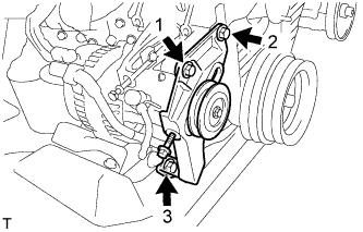
Temporarily install the compressor mounting bracket with the 4 bolts.
-
Using several steps, uniformly install and tighten the 4 bolts in the sequence shown in the illustration.
- Torque:
- 85 N*m { 870 kgf*cm, 63 ft.*lbf }
-
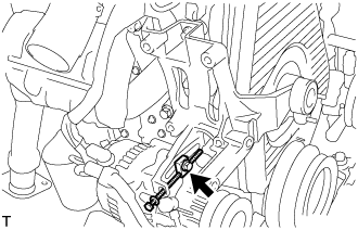
Temporarily tighten the bolt and spacer.
-
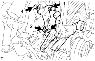
Temporarily install the compressor mounting bracket with the 3 bolts.
-
Using several steps, uniformly install and tighten the 3 bolts in the sequence shown in the illustration.
- Torque:
- 47 N*m { 475 kgf*cm, 36 ft.*lbf }
-
-
INSTALL COMPRESSOR AND MAGNETIC CLUTCH (w/ Air Conditioning System)
-
INSTALL FAN & GENERATOR V BELT (w/o Air Conditioning)
-
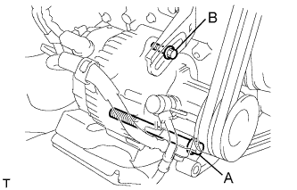
Install the V belt.
-
Using a bar, adjust the tension of the V belt.
-
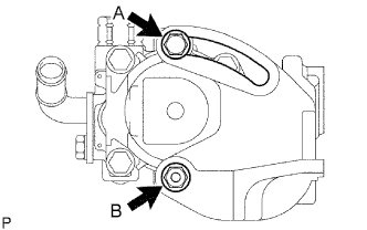
Tighten the bolts A and B.
- Torque:
- Bolt A
- 75 N*m { 765 kgf*cm, 55 ft.*lbf }
- Bolt B
- 18 N*m { 185 kgf*cm, 13 ft.*lbf }
-
Check the tension of the V belt. Click here
-
-
INSTALL FAN & GENERATOR V BELT (w/ Air Conditioning System)
-
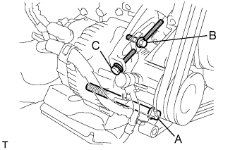
Install the V belt.
-
Tightening the bolt C, adjust the tension of the V belt.
-
Tighten the bolts A and B.
- Torque:
- Bolt A
- 75 N*m { 765 kgf*cm, 55 ft.*lbf }
- Bolt B
- 18 N*m { 185 kgf*cm, 13 ft.*lbf }
-
Check the tension of the V belt. Click here
-
-
INSTALL V (COOLER COMPRESSOR TO CRANKSHAFT PULLEY) BELT NO.1
-
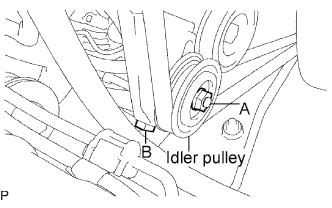
Install the V belt.
-
Tightening the bolt B, adjust the tension of the V belt.
-
Tighten nut A.
- Torque:
- 39 N*m { 400 kgf*cm, 29 ft.*lbf }
-
Check the tension of the V belt. Click here
-
-
INSTALL VANE PUMP V BELT (w/ Air Conditioning System)
-
Install the V belt.
-
Using a bar, adjust the tension of the V-ribbed belt.
-
Tighten the bolt A and nut B.
- Torque:
- Bolt (A)
- 48 N*m { 489 kgf*cm, 35 ft.*lbf }
- Nut (B)
- 64 N*m { 635 kgf*cm, 47 ft.*lbf }
-
Check the tension of the V belt. Click here
-
-
INSTALL WATER PUMP PULLEY
-
CONNECT RADIATOR HOSE NO.4
-
CONNECT RADIATOR HOSE INLET
-
ADD ENGINE COOLANT
-
Fill the radiator reservoir assembly with coolant to the top of the inlet.
Standard Capacity Item Specified Condition w/o Heater 12.3 liters (13.0 US qts, 10.8 Imp. qts) w/ Front Heater 13.3 liters (14.1 US qts, 11.7 Imp. qts) w/ Front and Rear Heaters 15.3 liters (16.2 US qts, 13.5 Imp. qts) Note
Do not substitute plain water for engine coolant.
Tech Tips
-
Use of improper coolants may damage the engine cooling system.
-
Use only Toyota Super Long Life Coolant or similar high quality ethylene glycol based non-silicate, non-amine, non-nitrite, and non-borate coolant with long-life hybrid organic acid technology (coolant with long-life hybrid organic acid technology consists of a combination of low phosphates and organic acids).
-
-
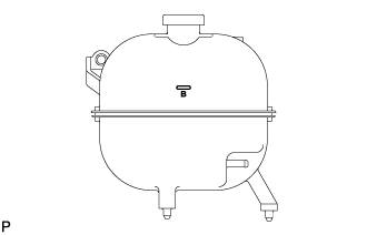
Add coolant up to the B line mark in the radiator reservoir assembly and install the reservoir cap.
-
Warm up the engine until the thermostat opens.
-
While the thermostat is open, circulate the coolant for several minutes.
Tech Tips
The thermostat open timing can be confirmed by pressing the inlet radiator hose by hand, and checking when the engine coolant starts to flow inside the hose.
-
-
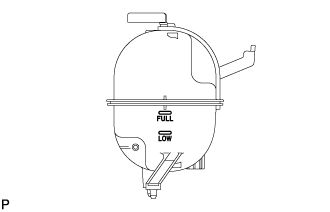
After the engine cools down, check that the coolant level is between the LOW and FULL level marks.
-
-
START THE ENGINE
-
CHECK FOR ENGINE COOLANT LEAKS
-
INSTALL ENGINE SERVICE HOLE SUB COVER SUB-ASSEMBLY
-
Install the 5 bolts and engine service hole cover.
- Torque:
- 13 N*m { 133 kgf*cm, 10 ft.*lbf }
-
-
INSTALL FRONT DOOR SCUFF PLATE RH
-
INSTALL FRONT SEAT ASSEMBLY RH
-
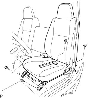
Connect the front seat inner belt assembly connector and install the front seat assembly.
-
Align the front seat assembly adjuster pin with the holes in the body.
-
Move the front seat assembly to the rearmost position.
Note
Make sure that the front seat assembly is securely locked.
-
Temporarily tighten the 2 bolts on the front side of the front seat assembly.
-
Move the front seat assembly fully forward.
Note
Make sure that the front seat assembly is securely locked.
-
Temporarily tighten the 2 bolts on the rear side of the front seat assembly.
-
Move the front seat assembly to the rearmost position.
Note
Make sure that the front seat assembly is securely locked.
-
Fully tighten the 2 bolts on the front side of the front seat assembly in the order of outer and inner side.
- Torque:
- 39 N*m { 398 kgf*cm, 29 ft.*lbf }
-
Move the front seat assembly fully forward.
Note
Make sure that the front seat assembly is securely locked.
-
Fully tighten the 2 bolts on the rear side of the front seat assembly in the order of outer and inner side.
- Torque:
- 39 N*m { 398 kgf*cm, 29 ft.*lbf }
-