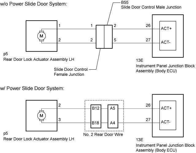
POWER DOOR LOCK CONTROL SYSTEM Slide Door Lock Motor LH Circuit
DESCRIPTION
The instrument panel junction block assembly (body ECU) receives the rear left door lock/unlock request signal from the door control switch or door key cylinder. The instrument panel junction block assembly (body ECU) actives the door lock motor on rear door lock actuator assembly LH according to the signal.
WIRING DIAGRAM
INSPECTION PROCEDURE
PROCEDURE
-
CHECK VEHICLE TYPE
-
Check the vehicle type.
Result Result Proceed to w/o Power Slide Door System A w/ Power Slide Door System B
B 
INSPECT REAR DOOR LOCK ACTUATOR ASSEMBLY LH Click here
A 
-
-
INSPECT REAR DOOR LOCK ACTUATOR ASSEMBLY LH
-
Remove the rear door lock actuator assembly LH Click here.
-
Inspect the rear door lock actuator assembly LH Click here.
NG 
REPLACE REAR DOOR LOCK ACTUATOR ASSEMBLY LH Click here
OK
-
-
INSPECT SLIDE DOOR CONTROL FEMALE JUNCTION
-
Disconnect the slide door control female junction connector.
-
Measure the resistance according to the value(s) in the table below.
Standard Resistance Tester Connection Condition Specified Condition A - 1 Always Below 1 Ω E - 2 Always Below 1 Ω
NG
REPLACE SLIDE DOOR CONTROL FEMALE JUNCTION
OK
-
-
INSPECT SLIDE DOOR CONTROL MALE JUNCTION
-
Remove the slide door control male junction connector.
-
Measure the resistance according to the value(s) in the table below.
Standard Resistance Tester Connection Condition Specified Condition A - 2 Always Below 1 Ω E - 5 Always Below 1 Ω
NG
REPLACE SLIDE DOOR CONTROL MALE JUNCTION
OK
-
-
CHECK HARNESS AND CONNECTOR (INSTRUMENT PANEL JUNCTION BLOCK ASSEMBLY [BODY ECU] - REAR DOOR LOCK ACTUATOR ASSEMBLY LH)
-
Disconnect the 13E instrument panel junction block assembly (body ECU) connector.
-
Disconnect the p5 rear door lock actuator assembly connector.
-
Measure the resistance according to the value(s) in the table below.
Standard Resistance Tester Connection Condition Specified Condition 13E-26 (ACT+) - p5-1 Always Below 1 Ω 13E-27 (ACT-) - p5-2 Always Below 1 Ω 13E-26 (ACT+) or p5-1 - Body ground Always 10 kΩ or higher 13E-27 (ACT-) or p5-2 - Body ground Always 10 kΩ or higher
NG
REPAIR OR REPLACE HARNESS OR CONNECTOR
OK 
PROCEED TO NEXT CIRCUIT INSPECTION SHOWN IN PROBLEM SYMPTOMS TABLE Click here
-
-
INSPECT REAR DOOR LOCK ACTUATOR ASSEMBLY LH
-
Remove the rear door lock actuator assembly LH Click here.
-
Inspect the rear door lock actuator assembly LH Click here.
NG
REPLACE REAR DOOR LOCK ACTUATOR ASSEMBLY LH Click here
OK
-
-
CHECK NO. 2 REAR DOOR WIRE
-
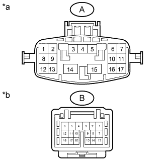
Text in Illustration *a No. 2 Rear Door Wire
(to Instrument panel junction block Assembly [Body ECU])
*b No. 2 Rear Door Wire
(to Rear Door Lock Actuator Assembly LH)
Disconnect the A and B No. 2 rear door wire connectors.
-
Measure the resistance according to the value(s) in the table below.
Standard Resistance Tester Connection Condition Specified Condition A-4 -B-18 Always Below 1 Ω A-5 - B-12 Always Below 1 Ω
NG
REPLACE NO. 2 REAR DOOR WIRE
OK
-
-
CHECK HARNESS AND CONNECTOR (INSTRUMENT PANEL JUNCTION BLOCK ASSEMBLY [BODY ECU] - REAR DOOR LOCK ACTUATOR ASSEMBLY LH)
-
Disconnect the 13E instrument panel junction block assembly (body ECU) connector.
-
Disconnect the p5 rear door lock actuator assembly connector.
-
Measure the resistance according to the value(s) in the table below.
Standard Resistance Tester Connection Condition Specified Condition 13E-26 (ACT+) - p5-2 Always Below 1 Ω 13E-27 (ACT-) - p5-3 Always Below 1 Ω 13E-26 (ACT+) or p5-2 - Body ground Always 10 kΩ or higher 13E-27 (ACT-) or p5-3 - Body ground Always 10 kΩ or higher
NG
REPAIR OR REPLACE HARNESS OR CONNECTOR
OK
PROCEED TO NEXT CIRCUIT INSPECTION SHOWN IN PROBLEM SYMPTOMS TABLE Click here
-