ENGINE UNIT INSTALLATION

PROCEDURE
-
INSTALL IGNITION COIL ASSEMBLY
-
INSTALL FUEL INJECTOR SEAL
-
INSTALL FUEL INJECTOR ASSEMBLY (for Direct Injection)
-
INSTALL FUEL DELIVERY PIPE RH
-
INSTALL FUEL DELIVERY PIPE WITH SENSOR ASSEMBLY LH
-
INSTALL NO. 2 FUEL PIPE SUB-ASSEMBLY
-
SET FUEL PUMP ASSEMBLY
-
TEMPORARILY INSTALL NO. 1 FUEL PIPE SUB-ASSEMBLY
-
INSTALL FUEL PUMP ASSEMBLY
-
INSTALL NO. 1 FUEL PIPE SUB-ASSEMBLY
-
INSTALL INTAKE MANIFOLD
-
INSTALL FUEL INJECTOR ASSEMBLY (for Port Injection)
-
INSTALL FUEL DELIVERY PIPE SUB-ASSEMBLY
-
INSTALL WIRE HARNESS CLAMP BRACKET
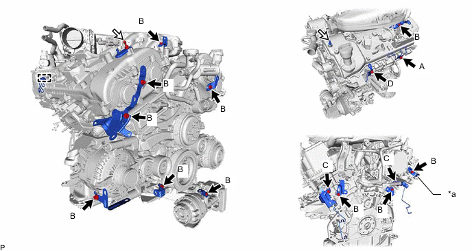
*a LHD only - - 
Bolt 
V-bank Cover Bracket
-
Install the wire harness clamp bracket to the cylinder head cover RH with the V-bank cover bracket.
- Torque:
- 10 N*m { 102 kgf*cm, 7 ft.*lbf }
-
Install the V-bank cover bracket to the cylinder head LH.
- Torque:
- 10 N*m { 102 kgf*cm, 7 ft.*lbf }
-
for LHD:
Install the 14 wire harness clamp brackets with the 15 bolts.
- Torque:
- for Bolt A
- 29 N*m { 296 kgf*cm, 21 ft.*lbf }
- for Bolt B
- 10 N*m { 102 kgf*cm, 7 ft.*lbf }
- for Bolt C
- 12 N*m { 122 kgf*cm, 9 ft.*lbf }
- for Bolt D
- 21 N*m { 214 kgf*cm, 15 ft.*lbf }
-
for RHD:
Install the 13 wire harness clamp brackets with the 14 bolts.
- Torque:
- for Bolt A
- 29 N*m { 296 kgf*cm, 21 ft.*lbf }
- for Bolt B
- 10 N*m { 102 kgf*cm, 7 ft.*lbf }
- for Bolt C
- 12 N*m { 122 kgf*cm, 9 ft.*lbf }
- for Bolt D
- 21 N*m { 214 kgf*cm, 15 ft.*lbf }
-
Install the wire harness clamp bracket to the wire harness protector of the cylinder head cover RH.
-
-
INSTALL ENGINE WIRE
-
INSTALL VACUUM PUMP ASSEMBLY
-
INSTALL INTAKE AIR SURGE TANK ASSEMBLY
-
INSTALL NO. 2 WATER BY-PASS PIPE ASSEMBLY
-
Connect the No. 2 water by-pass pipe assembly to the No. 1 water outlet pipe and slide the 2 hose clamps to secure the hose.
-
Install the No. 2 water by-pass pipe assembly with the 2 bolts.
- Torque:
- 21 N*m { 214 kgf*cm, 15 ft.*lbf }
-
-
INSTALL WATER BY-PASS PIPE ASSEMBLY
-
Install the water by-pass pipe assembly with the bolt and nut.
- Torque:
- 10 N*m { 102 kgf*cm, 7 ft.*lbf }
-
Install the 4 water by-pass hoses and slide the 4 hose clamps to secure the hose.
-
-
INSTALL WATER INLET CAP
-
Install the 2 water inlet caps and slide the 2 hose clamps to secure the cap.
-
-
INSTALL WATER HOSE SUB-ASSEMBLY
-
Install the 2 water hose sub-assembly and slide the 2 hose clamps to secure the hose.
-
-
INSTALL NO. 2 WATER BY-PASS HOSE
-
Install the No. 2 water by-pass hose and slide the 2 hose clamps to secure the hose.
-
-
INSTALL NO. 6 WATER BY-PASS HOSE
-
Install the No. 6 water by-pass hose and slide the 2 hose clamps to secure the hose.
-
-
INSTALL NO. 1 COMPRESSOR MOUNTING BRACKET
-
Install the No. 1 compressor mounting bracket with the 4 bolts.
- Torque:
- 43 N*m { 438 kgf*cm, 32 ft.*lbf }
-
-
INSTALL COMPRESSOR ASSEMBLY WITH PULLEY
-
INSTALL NO. 1 IDLER PULLEY SUB-ASSEMBLY
-
Install the No. 1 idler pulley sub-assembly with the bolt.
- Torque:
- 54 N*m { 551 kgf*cm, 40 ft.*lbf }
-
-
INSTALL V-RIBBED BELT TENSIONER ASSEMBLY
-
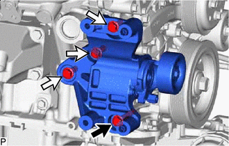
Bolt A Bolt B Install the V-ribbed belt tensioner assembly with the 4 bolts.
- Torque:
- 43 N*m { 438 kgf*cm, 32 ft.*lbf }
Standard Bolt Length Item Specified Condition Bolt A 70 mm (2.76 in.) Bolt B 35 mm (1.38 in.)
-
-
INSTALL GENERATOR ASSEMBLY
-
INSTALL FAN AND GENERATOR V BELT
-
INSTALL FRONT NO. 1 ENGINE MOUNTING BRACKET LH
-
Install the front No. 1 engine mounting bracket LH with the 4 bolts.
- Torque:
- 43 N*m { 438 kgf*cm, 32 ft.*lbf }
-
-
INSTALL FRONT NO. 1 ENGINE MOUNTING BRACKET RH
-
Install the front No. 1 engine mounting bracket RH with the 4 bolts.
- Torque:
- 43 N*m { 438 kgf*cm, 32 ft.*lbf }
-