AIR CONDITIONING SYSTEM, Diagnostic DTC:B1412/12
| DTC Code | DTC Name |
|---|---|
| B1412/12 | Ambient Temperature Sensor Circuit |
DESCRIPTION
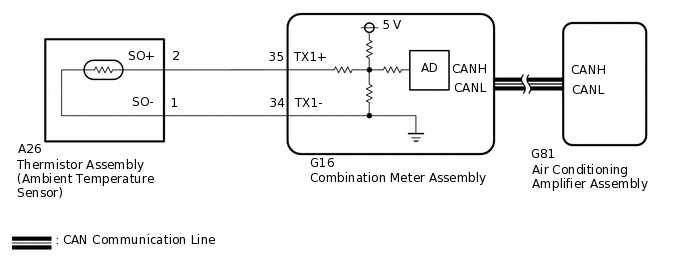
The thermistor assembly (ambient temperature sensor) is installed in front of the cooler condenser assembly to detect the ambient temperature which is used to control the air conditioning system AUTO mode. This sensor is connected to the air conditioning amplifier assembly and detects fluctuations in the ambient temperature. This data is used for controlling the cabin temperature. The sensor sends a signal to the air conditioning amplifier assembly. The resistance of the thermistor assembly (ambient temperature sensor) changes in accordance with the ambient temperature. As the temperature decreases, the resistance increases. Conversely, as the temperature increases, the resistance decreases.
The air conditioning amplifier assembly applies a voltage (5 V) to the thermistor assembly (ambient temperature sensor) and reads voltage changes due to changes in the resistance of the thermistor assembly (ambient temperature sensor).
DTC No. |
Detection Item |
DTC Detection Condition |
Trouble Area |
Memory |
Note |
|---|---|---|---|---|---|
B1412/12 |
Ambient Temperature Sensor Circuit |
|
|
Memorized (4 seconds or more) |
- |
The air conditioning amplifier assembly stores the DTC of the respective malfunction if it has occurred for the period of time indicated in the parentheses.
If the ambient temperature is approximately -52.9°C (-63.22°F) or less, DTC B1412/12 may be output even though the system is normal.
WIRING DIAGRAM
CAUTION / NOTICE / HINT
The air conditioning system uses the CAN communication system. Inspect the communication function by following How to Proceed with Troubleshooting. Troubleshoot the air conditioning system after confirming that the communication system is functioning properly.
When the servo motor or air conditioning amplifier assembly is replaced, be sure to perform servo motor initialization.
PROCEDURE
READ VALUE USING GTS (AMBIENT TEMP SENSOR)
Connect the GTS to the DLC3.
Turn the power switch on (IG).
Turn the GTS on.
Enter the following menus: Body Electrical / Air Conditioner / Data List.
Check the value(s) by referring to the table below.
Body Electrical > Air Conditioner > Data List
Tester Display
Measurement Item
Range
Normal Condition
Diagnostic Note
Ambient Temp Sensor
Thermistor assembly (ambient temperature sensor)
Min.: -23.30°C (-9.94°F)
Max.: 65.95°C (150.71°F)
Actual ambient temperature displayed
Thermistor assembly (ambient temperature sensor) system malfunction:
When open circuit: -23.30°C (-9.94°F)
When short circuit: 65.95°C (150.71°F)
Body Electrical > Air Conditioner > Data List
Tester Display
Ambient Temp Sensor
OK
The display is as specified in the normal condition column.
Result
Result
Proceed to
OK (When troubleshooting according to Problem Symptoms Table)
A
OK (When troubleshooting according to the DTC)
B
NG
C
INSPECT THERMISTOR ASSEMBLY (AMBIENT TEMPERATURE SENSOR)
Remove the thermistor assembly (ambient temperature sensor).
Inspect the thermistor assembly (ambient temperature sensor).
Result
Proceed to
OK
NG
CHECK HARNESS AND CONNECTOR (THERMISTOR ASSEMBLY [AMBIENT TEMPERATURE SENSOR] - AIR CONDITIONING AMPLIFIER ASSEMBLY)
Disconnect the A26 thermistor assembly (ambient temperature sensor) connector.
Disconnect the G16 combination meter assembly connector.
Measure the resistance according to the value(s) in the table below.
Standard Resistance
Tester Connection
Condition
Specified Condition
A26-2 (SO+) - G16-35 (TX1+)
Always
Below 1 Ω
A26-1 (SO-) - G16-34 (TX1-)
Always
Below 1 Ω
A26-2 (SO+) - A26-1 (SO-)
Always
10 kΩ or higher
A26-2 (SO+) or G16-35 (TX1+) - Body ground
Always
10 kΩ or higher
A26-1 (SO-) or G16-34 (TX1-) - Body ground
Always
10 kΩ or higher
Result
Proceed to
OK
NG
NG REPAIR OR REPLACE HARNESS OR CONNECTOR