ENGINE UNIT
-
CONSTRUCTION
-
For in-line 4-cylinder engines, the main cause of vibration is the imbalanced inertial forces of reciprocating parts such as the pistons and connecting rods. Engine vibration has been reduced by using 2 balance shafts to cancel the imbalanced inertial forces, thereby reducing engine noise (booming noise).
-
The 2 balance shafts are built into the cylinder block. Using a chain, sprockets and gears, both balance shafts rotate at twice the speed of the crankshaft, with each balance shaft rotating in the opposite direction of the other.
-
The chain tensioner uses a spring and oil pressure to maintain proper chain tension at all times. A ratchet type non-return mechanism is also included.
-
The chain tensioner has 2 oil holes that spray engine oil for lubricating the balance shaft chain. Furthermore, they lubricate the timing chain that drives the camshaft.
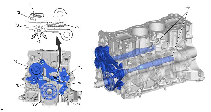
*1 Cam Spring *2 Cam *3 Plunger *4 Spring *5 Balance Shaft Drive Gear Sub-assembly *6 Balance Shaft Driven Gear *7 No. 2 Crankshaft Timing Sprocket *8 Balance Shaft Chain (No. 2 Chain Sub-assembly) *9 No. 2 Chain Tensioner Assembly *10 Balance Shaft Timing Sprocket *11 Balance Shaft - - 
Engine Oil - -
-
-
OPERATION
-
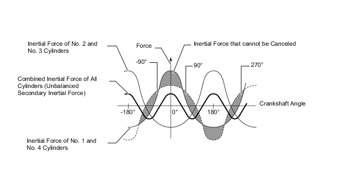
In the in-line 4-cylinder engine, the crankshaft angles for the No. 1 and No. 4 cylinders are at the exact opposite (180°) positions of the No. 2 and No. 3 cylinders. Therefore, the inertial forces of the pistons and connecting rods of the former and latter 2 cylinders almost cancel each other out. However, because the position at which the piston reaches its maximum speed is located toward the top dead center from the center of the stroke, the upward inertial force is greater than the downward inertial force. This unbalanced secondary inertial force is generated twice for each rotation of the crankshaft.
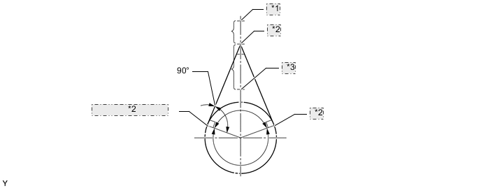
*1 Top Dead Center *2 Point of Max. Speed *3 Bottom Dead Center Figure 1. Inertial Force Generated by 4 In-line Cylinders
-
To cancel the unbalanced secondary inertial force, 2 balance shafts are rotated twice for each rotation of the crankshaft and generate inertial force in the opposite direction. Also, in order to cancel the inertial force generated by the balance shaft itself, the balance shaft actually consists of 2 shafts rotating in opposite directions.
Figure 2. Mass Direction of Balance Shaft at Crankshaft Angle
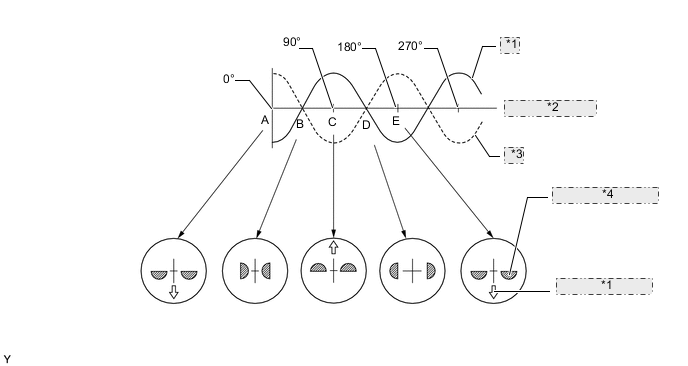
*1 Inertial Force of Balancer *2 Crankshaft Angle *3 Secondary Inertial Force *4 Mass Direction of Balance Shaft
-