THEFT DETERRENT SYSTEM Intrusion Sensor Cancel Switch Circuit
DESCRIPTION
When the intrusion sensor cancel switch on the map light assembly is pressed, the sensor off signal is sent to the body ECU which causes the intrusion sensor to stop operating.
WIRING DIAGRAM
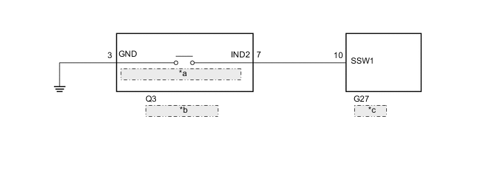
| *a | Intrusion Sensor Cancel Switch |
| *b | Map Light Assembly |
| *c | Body ECU |
CAUTION / NOTICE / HINT
Note
-
Inspect the fuses for circuits related to this system before performing the following procedure.
-
w/ Door control Battery:
As the door control battery is installed between the vehicle battery and body ECU, first perform the inspections to confirm that there are no malfunctions in the power source circuit for the body ECU before performing this troubleshooting procedure.
-
w/ Automatic Light Control System:
If the body ECU has been replaced, it is necessary to initialize the body ECU.
PROCEDURE
-
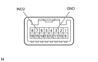
CHECK HARNESS AND CONNECTOR (BODY ECU - MAP LIGHT ASSEMBLY AND BODY GROUND)
-
Disconnect the G27 body ECU connector.
-
Disconnect the Q3 map light assembly connector.
-
Measure the resistance according to the value(s) in the table below.
Standard Resistance Tester Connection Condition Specified Condition G27-10 (SSW1) - Q3-7 (IND2) Always Below 1 Ω Q3-3 (GND) - Body ground Always Below 1 Ω G27-10 (SSW1) - Body ground Always 10 kΩ or higher Q3-7 (IND2) - Body ground Always 10 kΩ or higher Result Proceed to OK NG
NG 
REPAIR OR REPLACE HARNESS OR CONNECTOR
OK 
-
-
INSPECT MAP LIGHT ASSEMBLY (INTRUSION SENSOR CANCEL SWITCH)
-
Remove the map light assembly (intrusion sensor cancel switch).
-
Measure the resistance according to the value(s) in the table below.
Standard Resistance Tester Connection Condition Specified Condition 7 (IND2) - 3 (GND) Intrusion sensor cancel switch not pressed 10 kΩ or higher 7 (IND2) - 3 (GND) Intrusion sensor cancel switch pressed Below 1 Ω Result Proceed to OK (for LHD) OK (for RHD) NG
OK (for LHD)
REPLACE BODY ECU Click here
OK (for RHD)
REPLACE BODY ECU Click here
NG
REPLACE MAP LIGHT ASSEMBLY (INTRUSION SENSOR CANCEL SWITCH) Click here
-