BODY STRUCTURE
-
CONSTRUCTION
-
Aerodynamic parts are provided on various parts of the vehicle and the Cd level* is reduced to achieve improved fuel efficiency.
Tech Tips
*: The Cd level refers to the air resistance coefficient. Cd stands for Constant drag. The lower the level is, the lesser the air resistance is. This improves fuel efficiency.
-
On models for Europe, an aero fin which adjusts airflow is located on the fuel tank protector No. 1 and front floor cover RH to smooth the flow of air which enters at the front of the vehicle and flows under the floor. Smooth airflow in the lower surface of the vehicle enhances the speed of airflow and a low pressure region is created between the vehicle and the road surface (Venturi effect). This low pressure region attracts the vehicle to the road surface, thus causing down force. Thus, superior straight-line stability has been achieved.
Figure 1. Under Cover (Models with 3ZR-FAE Engine)
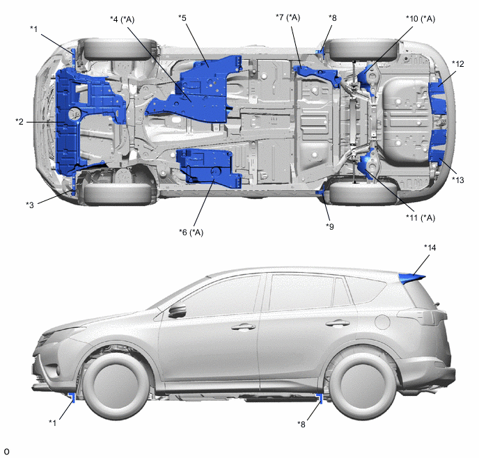
*A Models for Europe - - *1 Front Fender Splash Shield Front LH *2 Engine Under Cover No. 1 *3 Front Fender Splash Shield Front RH *4 Front Floor Cover *5 Fuel Tank Protector No. 1 *6 Front Floor Cover RH *7 Floor Under Cover No. 1 *8 Rear Wheel House Plate Front LH *9 Rear Wheel House Plate Front RH *10 Rear Suspension Arm Cover LH *11 Rear Suspension Arm Cover RH *12 Luggage Compartment Service Cover Protector No. 2 *13 Luggage Compartment Service Cover Protector No. 1 *14 Rear Spoiler Figure 2. Under Cover (Models without 3ZR-FAE Engine)
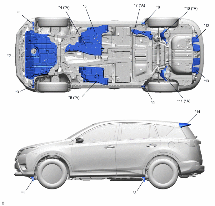
*A Models for Europe - - *1 Front Fender Splash Shield Front LH *2 Engine Under Cover No. 1 *3 Front Fender Splash Shield Front RH *4 Front Floor Cover *5 Fuel Tank Protector No. 1 *6 Front Floor Cover RH *7 Floor Under Cover No. 1 *8 Rear Wheel House Plate Front LH *9 Rear Wheel House Plate Front RH *10 Rear Suspension Arm Cover LH *11 Rear Suspension Arm Cover RH *12 Luggage Compartment Service Cover Protector No. 2 *13 Luggage Compartment Service Cover Protector No. 1 *14 Rear Spoiler -
An aero stabilizing fin is provided on the outer rear view mirror assembly and a type of aerodynamic technology known as a vortex generator is used for the fin. Small vortexes are purposely generated in airflow to push the vehicle from the left and right sides, thus achieving excellent operation stability.
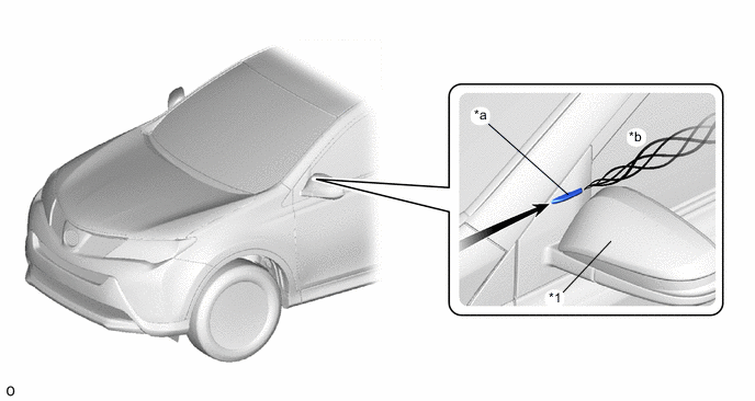
*1 Outer Rear View Mirror Assembly - - *a Aero Stabilizing Fin *b Generated Vortices -
An air-kick shape is provided on the lens surface of the rear combination light assembly. The air-kick shape cuts and sends airflow rearward to suppress vortices, and air resistance is reduced by airflow adjustment which smooth the airflow.
-
An aero stabilizing fin is provided on the lens surface of the rear combination light assembly and a type of aerodynamic technology known as a vortex generator is used for the fin. Small vortexes are purposely generated in airflow to push the vehicle from the left and right sides, thus achieving excellent operation stability.
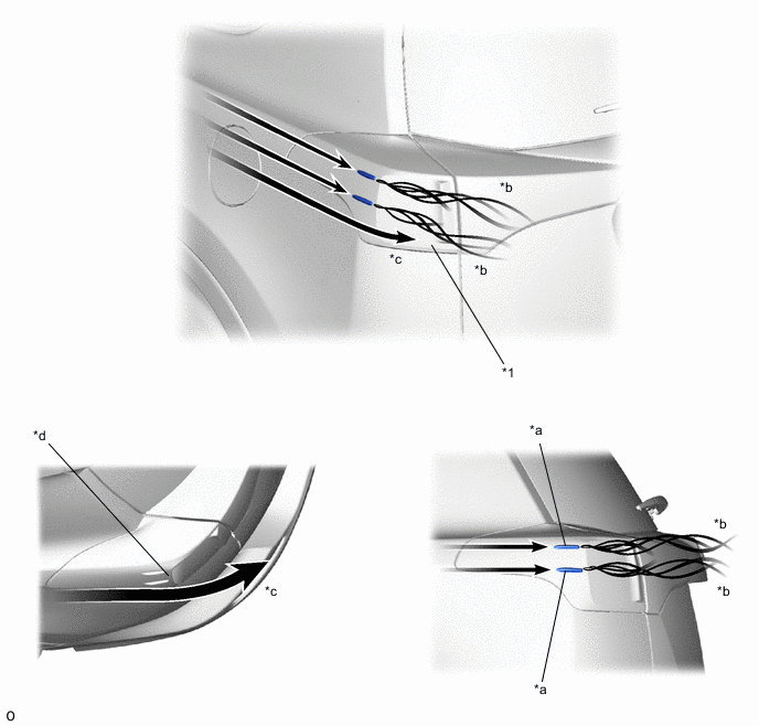
*1 Rear Combination Light - - *a Aero Stabilizing Fin *b Generated Vortices *c Generated Vortices *d Air-kick Shape
-