Install the cylinder block tight plug to the cylinder head sub-assembly.
INSTALL PISTON
Gradually heat each piston and connecting rod to approximately 100 °C (212 °F).
Coat the piston, piston pin and connecting rod with engine oil.
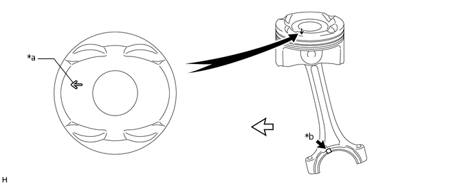
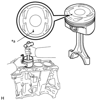
Align the front mark of the piston and the groove of the connecting rod as shown in the illustration and insert the connecting rod into the piston.
*a
Front Mark
*b
Groove
Intake Side
-
-
Tip:
The piston and piston pin are a matched set.
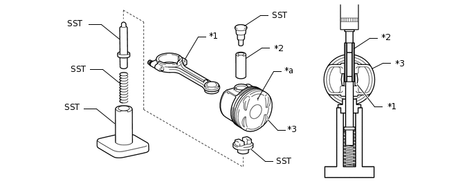
Using SST and a press, install the piston pin.
Note:
Make sure to install the piston pin so that it is longitudinally centered in the connecting rod.
09221-25026
09221-00021
09221-00030
09221-21010
09221-02100
09221-02200
09221-02300
*1
Connecting Rod
*2
Piston Pin
*3
Piston
-
-
*a
Front Mark
-
-
Note:
Press in the piston pin while applying engine oil to the piston, piston pin and connecting rod.
Be sure to set SST (bushing) as shown in the illustration.
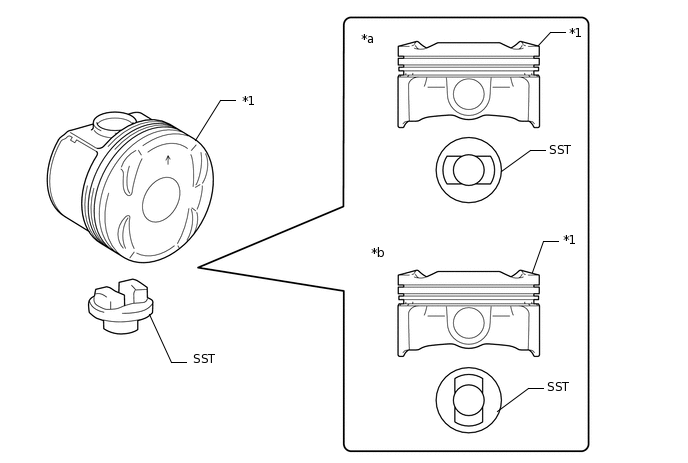
*1
Piston
-
-
*a
Correct
*b
Incorrect
Tip:
Press in the piston pin from the side of the piston with the front mark as shown in the illustration.
With the connecting rod fully inserted into the piston end, press in the piston pin until it is flush with the piston surface.
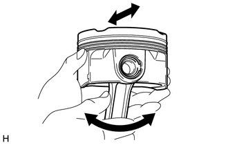
Check the fitting condition between the piston and piston pin.
Move the connecting rod back and forth on the piston pin. Check the fitting condition. If any abnormal movement is felt, replace the piston and piston pin.
Rotate the piston back and forth on the piston pin. Check the fitting condition. If any abnormal movement is felt, replace the piston and piston pin.
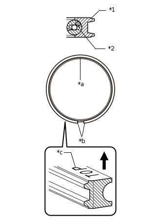
INSTALL PISTON RING SET
*1
Oil Ring
*2
Oil Ring Expander
*a
Coil Joint
*b
Oil Ring End
*c
Mark (TOP)
Upward
Install the oil ring expander and oil ring by hand.
Note:
Install the oil ring with the mark (TOP) facing upward.
Install the oil ring expander and oil ring so that their ring ends are at opposite sides.
Securely install the oil ring expander into the inner groove of the oil ring.
*1
No. 1 Compression Ring
*2
No. 2 Compression Ring
*3
Piston Ring Expander
*a
Mark (TOP)
Upward
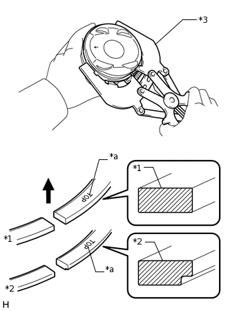
Using a piston ring expander, install the No. 1 compression ring and No. 2 compression ring as shown in the illustration.
Note:
Install the compression rings with the mark (TOP) facing upward.
*1
No. 1 Compression Ring
*2
No. 2 Compression Ring
*3
Oil Ring
Engine Front
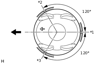
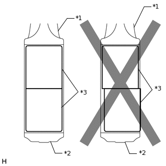
Position the piston rings so that the ring ends are as shown in the illustration.
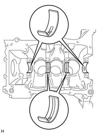
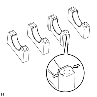
INSTALL CRANKSHAFT BEARING
Clean the main journal and both surfaces of the crankshaft bearing and No. 2 crankshaft bearing.
Install the crankshaft bearing to the cylinder block sub-assembly as shown in the illustration.
Note:
Make sure to install each crankshaft bearing to the correct position as shown in the illustration.
Do not apply engine oil to the crankshaft bearings or the contact surfaces.
Both sides of the oil groove in the cylinder block sub-assembly should be visible through the oil feed holes in the crankshaft bearing. The amount visible on each side of the holes should be equal.
Do not allow coolant to come into contact with the crankshaft bearing inner surface.
If any coolant comes into contact with the crankshaft bearing inner surface, replace the crankshaft bearing with a new one.
Install the No. 2 crankshaft bearing to the crankshaft bearing cap.
Note:
Do not apply engine oil to the crankshaft bearings or the contact surfaces.
Do not allow coolant to come into contact with the crankshaft bearing inner surface.
If any coolant comes into contact with the crankshaft bearing inner surface, replace the crankshaft bearing with a new one.
Install the connecting rod bearing cap to the connecting rod sub-assembly.
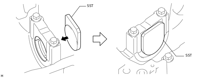
Using SST, align the crankshaft bearing with the No. 2 crankshaft bearing.
0109-4
0109-4E
Note:
Make sure the crankshaft bearing and No. 2 crankshaft bearing are aligned properly.
Remove the connecting rod bearing cap from the connecting rod sub-assembly.
INSTALL CRANKSHAFT THRUST WASHER
*a
Oil Groove
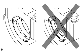
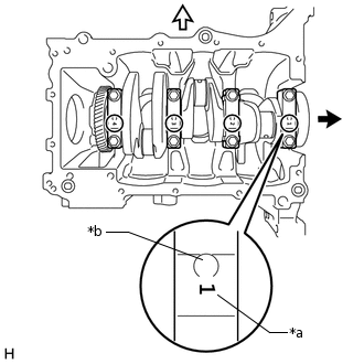
Apply engine oil to the crankshaft thrust washers.
Install the 2 crankshaft thrust washers to the No. 2 journal position of the cylinder block sub-assembly with the oil grooves facing outward.
INSTALL CRANKSHAFT
*a
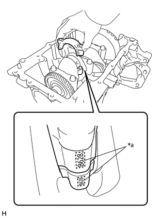
Number Mark
*b
Groove
Flywheel Side
Exhaust Side
Apply engine oil to the crankshaft bearing, and place the crankshaft on the cylinder block sub-assembly.
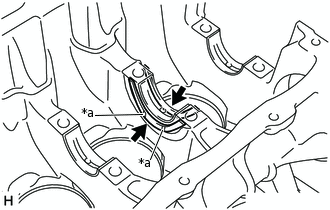
Confirm the number marks, and install crankshaft bearing caps to the cylinder block sub-assembly with the grooves positioned toward the exhaust side.
Note:
Install the crankshaft bearing caps in numerical order starting from the flywheel side.
Make sure the grooves of the crankshaft bearing caps are positioned toward the exhaust side.
Apply a light coat of engine oil to the threads and under the heads of the crankshaft bearing cap set bolts.
Install the crankshaft bearing cap bolts.
Tip:
The crankshaft bearing cap bolts are tightened in 2 progressive steps.
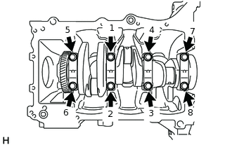
Step 1:
Uniformly tighten the 8 crankshaft bearing cap bolts in the order shown in the illustration.
20 N*m
204 kgf*cm
15 ft.*lbf
If a crankshaft bearing cap bolt cannot be tightened to the specified torque, replace it.
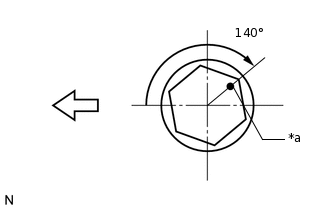
Step 2:
Mark the front of the crankshaft bearing cap bolts with paint.
*a
Paint Mark
Engine Front
Tighten the crankshaft bearing cap bolts 140° as shown in the illustration.
Clean the connecting rod bearing contact surface of the connecting rod and connecting rod cap, and both surfaces of both connecting rod bearings.
Install the connecting rod bearings to the connecting rods.
Note:
Do not apply engine oil to the connecting rod bearings or the contact surfaces.
Do not allow coolant to come into contact with the connecting rod bearing inner surface.
If any coolant comes into contact with the connecting rod bearing inner surface, replace the connecting rod bearing with a new one.
Install the connecting rod bearings to the connecting rod caps.
Note:
Do not apply engine oil to the connecting rod bearings or the contact surfaces.
Do not allow coolant to come into contact with the connecting rod bearing inner surface.
If any coolant comes into contact with the connecting rod bearing inner surface, replace the connecting rod bearing with a new one.
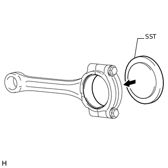
Install the connecting rod bearing cap to the connecting rod sub-assembly.
Using SST, align the 2 connecting rod bearings.
0109-4
0109-4C
*1
Connecting Rod Sub-assembly
*2
Connecting Rod Bearing Cap
*3
Connecting Rod Bearing
Note:
make sure both of the connecting rod bearings are aligned properly.
Remove the connecting rod bearing cap from the connecting rod sub-assembly.
INSTALL PISTON WITH CONNECTING ROD
*1
No. 1 Compression Ring
*2
No. 2 Compression Ring
*3
Oil Ring
Engine Front
Apply engine oil to the cylinder walls, pistons, and surfaces of the connecting rod bearings.
Position the piston rings so that the ring ends are as shown in the illustration.
Note:
Do not align the ring ends.
*a
Front Mark
Using a piston ring compressor, push the correctly numbered piston sub-assembly and connecting rod sub-assembly into the cylinder with the front marks of the piston facing forward.
*a
Match Marks
Align the connecting rod cap shear end with the connecting rod shear end and install the connecting rod bearing caps.
Note:
Make sure to match the marks of the connecting rod cap and connecting rod sub-assembly.
Apply a light coat of engine oil to the threads and under the heads of the 2 connecting rod bolts.
Install the connecting rod cap bolts.
Tip:
The connecting rod cap bolts are tightened in 3 progressive steps.
Step 1:
Temporarily tighten the connecting rod cap bolts.
5.0 N*m
51 kgf*cm
44 in.*lbf
Step 2:
Tighten the connecting rod bolts.
15 N*m
153 kgf*cm
11 ft.*lbf
Step 3:
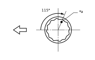
Mark the front of the crankshaft bearing cap bolts with paint.
*a
Paint Mark
Engine Front
Tighten the connecting rod bolts by 115° as shown in the illustration.
Check that the crankshaft turns smoothly.
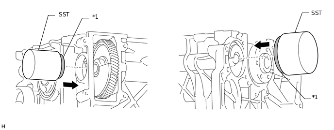
INSTALL NO. 1 AND NO. 2 BALANCESHAFT BEARING
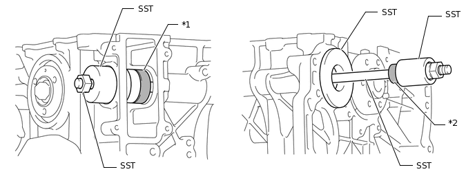
Using SST, set the No. 1 Balanceshaft Bearing to the crank pulley side and No. 2 Balanceshaft Bearing to the flywheel side of the cylinder block.
0109-4
0109-4F
*1
No. 1 Balanceshaft Bearing
*2
No. 2 Balanceshaft Bearing
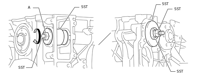
Turn the bolt (A) of SST clockwise to install the No. 1 and No. 2 Balanceshaft Bearing to the cylinder block.
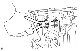
Using snap ring pliers, Install the stop-ring.
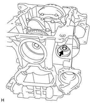
INSTALL NO. 1 BALANCESHAFT
Install the No. 1 balanceshaft to the cylinder block as shown in the illustration.
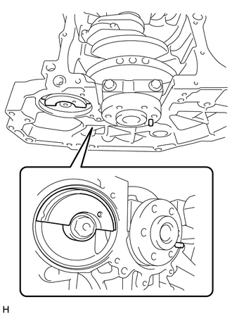
Turn the crankshaft and No. 1 balanceshaft so that they are positioned as shown in the illustration.
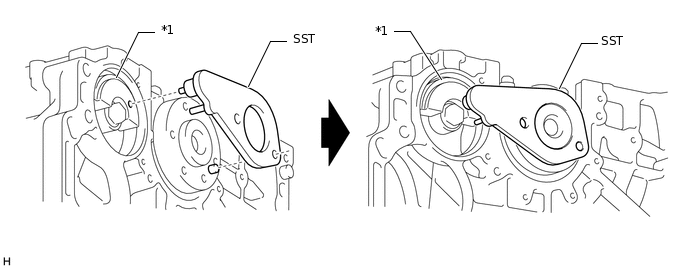
Using SST, secure the crankshaft and No. 1 balanceshaft.
0109-4
0109-4B
Note:
Check that SST is correctly positioned on the balanceshaft weight as shown in the illustration.
*1
NO. 1 Balanceshaft
-
-
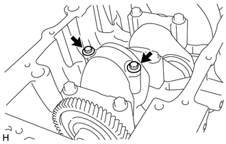
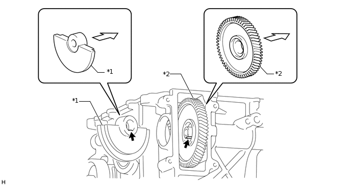
Position the balance weight as shown in the illustration, and install the balance weight and No. 1 balanceshaft driven gear with the bolt.
CAUTION:
Align the flat portion (A) of the balance weight and No. 1 balanceshaft.
Note:
Make sure the balance weight and No. 1 balanceshaft driven gear are oriented correctly.
*1
Balance Weight
*2
No. 1 Balanceshaft Driven Gear
Flat Portion (A)
Orientation
Using an E12 "TORX" socket wrench, install the bolt.
Tip:
The bolt is tightened in 2 progressive steps.
Step 1:
Tighten the bolt.
15 N*m
153 kgf*cm
11 ft.*lbf
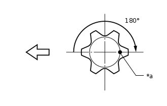
Step 2:
Mark the front of the bolt with paint.
*a
Paint Mark
Engine Front
Tighten the bolt 180° as shown in the illustration.
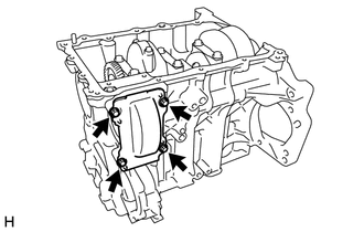
Install the cylinder block side cover with the 4 bolts.
8.0 N*m
82 kgf*cm
71 in.*lbf
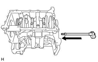
Using SST and a plastic hammer, install new cylinder block tight plugs.