LANE DEPARTURE ALERT SYSTEM Lane Departure Alert System Circuit
| DTC Code | DTC Name |
|---|---|
| Lane Departure Alert System Circuit |
DESCRIPTION
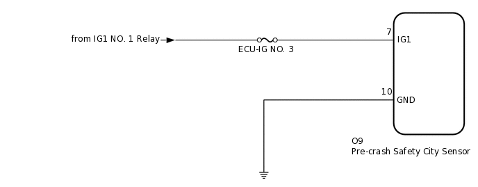
When the ignition switch is ON, power is supplied to the pre-crash safety city sensor.
WIRING DIAGRAM
CAUTION / NOTICE / HINT
Inspect the fuses for circuits related to this system before performing the following procedure.
PROCEDURE
INSPECT BATTERY VOLTAGE
Measure the battery voltage with the ignition switch off.
Standard voltage
11 to 14 V
Using the parts location and system diagram, check the system for blown-out fuses, open or short circuits in the wire harness(es) and connectors that are not properly connected by performing a visual check.
Tip:If the voltage is 11 V or less, replace or recharge the battery before proceeding to the next step.
Result
Proceed to
NEXT
CHECK PRE-CRASH SAFETY CITY SENSOR
Check pre-crash safety city sensor.
Note:DTCs may be output when connectors are disconnected during inspection. Therefore, make sure to clear the DTCs using the GTS once the inspection has been completed.
-
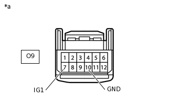
*a
Front view of wire harness connector
(to Pre-crash Safety City Sensor)
Disconnect the pre-crash safety city sensor connector.
Measure the voltage according to the value(s) in the table below.
Standard Voltage
Tester Connection
Condition
Specified Condition
O9-7 (IG1) - Body ground
Ignition switch ON
11 to 14 V
O9-7 (IG1) - Body ground
Ignition switch off
Below 1 V
Measure the resistance according to the value(s) in the table below.
Standard Resistance
Tester Connection
Condition
Specified Condition
O9-10 (GND) - Body ground
Always
Below 1 Ω
-
Result
Proceed to
OK
NG
NG REPAIR OR REPLACE HARNESS OR CONNECTOR
CHECK CAN COMMUNICATION SYSTEM
Use the GTS to check if the CAN communication system is functioning normally.
Result
Result
Proceed to
CAN communication system DTCs are not output
A
CAN communication system DTCs are output
B