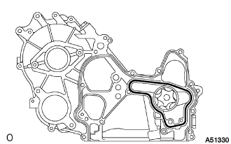
МАСЛЯНЫЙ НАСОС СНЯТИЕ

-
REMOVE ENGINE ASSEMBLY
-
REMOVE VANE PUMP ASSEMBLY
-
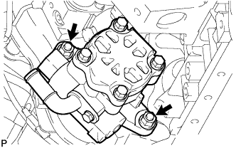
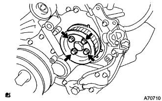
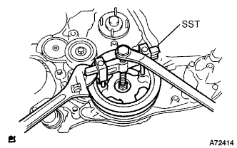
Отверните 2 гайки и снимите лопастной насос в сборе.
-
Снимите кольцевое уплотнение лопастного насоса с лопастного насоса в сборе.
-
-
REMOVE TIMING BELT COVER NO.1
-
Remove the wire harness clamp.
-
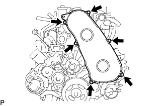
Remove the 6 bolts and timing belt cover No.1.
-
-
REMOVE TIMING BELT
-
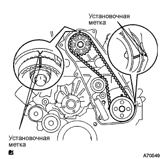
Turn the crankshaft in the clockwise direction and align the timing marks as shown in the illustration.
-
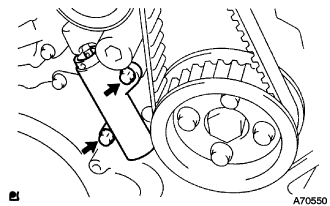
Uniformly loosen the 2 bolts, and remove the chain tensioner assembly No.1.
-
Remove the timing belt.
-
-
REMOVE FAN PULLEY
-
Отверните 4 гайки и снимите шкив вентилятора.
-
-
REMOVE EGR PIPE SUB-ASSEMBLY NO.1.
-
Отсоедините разъем датчика давления в топливной системе.
-
Выверните 2 болта, отверните 2 гайки и снимите трубу РОГ.
-
Снимите 2 прокладки.
-
-
REMOVE OIL LEVEL GAGE GUIDE
-
Снимите щуп проверки уровня масла.
-
Выверните болт и снимите трубку щупа проверки уровня масла.
-
-
REMOVE INJECTION PIPE
- SST
- 09023-12701
-
Remove the injection pipe.
-
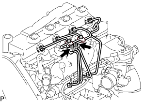
Remove the 2 nuts and injection pipe clamp No.3.
-
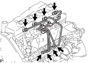
Using SST, remove the 4 injection pipes.
- SST
- 09023-12701
-
-
REMOVE FUEL INLET PIPE SUB-ASSEMBLY
-
Using SST, remove the fuel inlet pipe sub-assembly.
- SST
- 09023-12701
-
-
REMOVE INJECTION OR SUPPLY PUMP ASSEMBLY
-
Remove the 4 bolts.
-
Remove the camshaft timing pulley flange No.2 and pump drive shaft pulley.
-
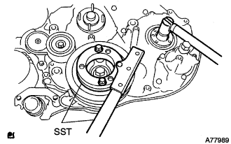
Using SST, remove the supply pump gear set nut and O-ring while holding the crankshaft pulley.
- SST
- 09213-58013
- 09330-00021
-
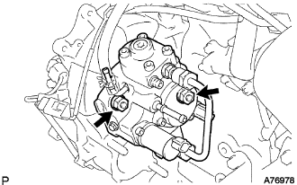
Disconnect the 2 fuel hoses.
-
Disconnect the 2 connectors and wire harness.
-
Loosen the 2 nuts as shown in the illustration.
-
Using SST, disengage the supply pump from the supply pump gear.
- SST
- 09950-50013 ( 09951-05010, 09952-05010, 09953-05020, 09954-05021 )
-
Remove the 2 nuts and supply pump from the engine.
-
Remove the O-ring from the supply pump.
-
Remove the pulley key from the supply pump.
-
-
REMOVE COMPRESSOR BRACKET
-
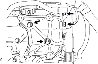
Выверните 4 болта и снимите кронштейн компрессора.
-
-
REMOVE IDLE PULLEY ASSEMBLY
-
Выверните болт и снимите шайбы и опорный ролик в сборе.
-
-
REMOVE GENERATOR BRACKET
-
Выверните 2 болта и снимите кронштейн генератора.
-
-
REMOVE GENERATOR ASSEMBLY
-
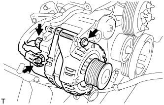
Disconnect the generator connector.
-
Remove the terminal cap.
-
Remove the nut and disconnect the wire harness from terminal B.
-
Remove the bolt and generator assembly.
-
-
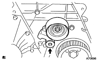
REMOVE V-RIBBED BELT TENSIONER ASSEMBLY
-
Выверните 4 болта и снимите натяжитель ремня в сборе.
-
-
REMOVE TIMING BELT IDLER SUB-ASSEMBLY NO.1
-
С помощью торцевого гаечного ключа на 10 мм выверните болт и снимите плоскую шайбу и опорный ролик приводного ремня газораспределения № 1.
-
-
REMOVE CRANKSHAFT PULLEY
-
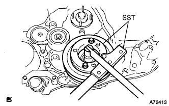
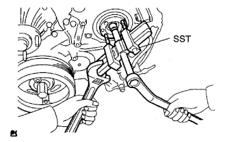
Выверните болт, удерживая коленчатый вал с помощью SST.
- SST
- 09213-58013
- 09330-00021
-
Вверните технологический болт.
-
С помощью SST снимите шкив коленчатого вала.
- SST
- 09950-50013 ( 09951-05010, 09952-05010, 09953-05020, 09954-05021 )
-
-
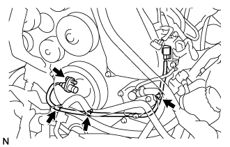
REMOVE VACUUM PUMP ASSEMBLY
-
Сдвиньте зажим и отсоедините 2 вакуумных шланга от вакуумного насоса.
-
Выверните пустотелый соединительный болт-штуцер и снимите штуцер вакуумного насоса и 2 прокладки.
-
Отверните 2 гайки и снимите вакуумный насос с двигателя.
-
Снимите 2 кольцевых уплотнения.
-
-
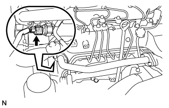
REMOVE CAMSHAFT POSITION SENSOR
-
Disconnect the camshaft position sensor connector.
-
Remove the bolt and the camshaft position sensor.
-
-
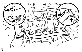
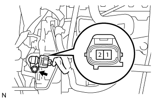
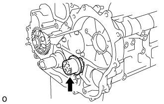
REMOVE CRANKSHAFT POSITION SENSOR
-
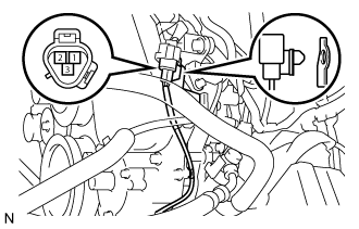
Disconnect the crankshaft position sensor connector.
-
Separate the connector from the vacuum pipe No.1.
-
Separate the 3 wire harness clamps.
-
Remove the bolt and the crankshaft position sensor.
-
-
REMOVE ENGINE OIL LEVEL SENSOR
-
Выверните 4 болта и снимите датчик уровня моторного масла.
-
-
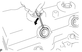
REMOVE OIL FILLER CAP SUB-ASSEMBLY
-
Remove the oil filler cap from the cylinder head cover.
-
-
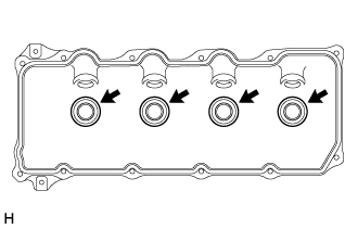
REMOVE NOZZLE HOLDER SEAL
-
Using a screwdriver, remove the holder seals by prying the portion between the holder seal and the cutout part of the cylinder head.
-
-
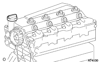
REMOVE CYLINDER HEAD COVER SUB-ASSEMBLY
-
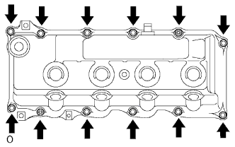
Remove the 10 bolts, 2 nuts, cylinder head cover and the cylinder head cover gasket.
-
Remove the 4 No. 3 cylinder head cover gaskets from the cylinder head cover.
-
-
REMOVE CAMSHAFT TIMING PULLEY
-
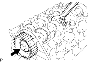
Remove the bolt for the camshaft timing pulley by holding the camshaft with a wrench.
-
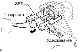
Using SST, remove the camshaft timing pulley and set key.
- SST
- 09950-40011 ( 09951-04010, 09952-04010, 09953-05010, 09957-04010 )
- 09955-04150
-
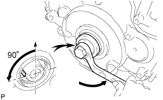
Rotate the crankshaft about 90° counterclockwise from the TDC position to lower the piston.
-
-
REMOVE TIMING BELT COVER NO.2
-
Remove the nut, 4 bolts and timing belt No.2 cover.
-
-
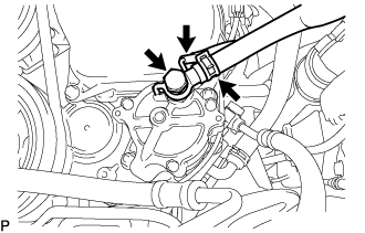
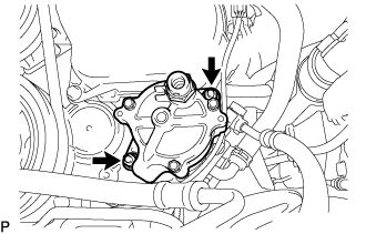
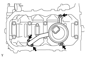
REMOVE WATER PUMP ASSEMBLY
-
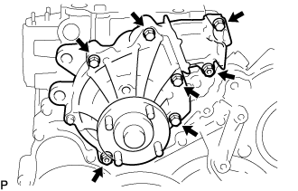
Remove the 5 bolts, 2 nuts, water pump and gasket.
-
-
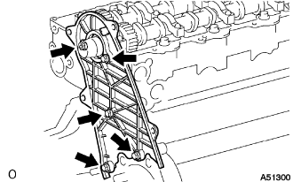
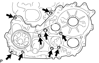
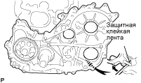
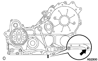
REMOVE TIMING GEAR CASE
-
Remove the 14 bolts and 2 nuts.
-
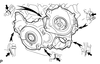
Pry the gear case in the location shown in the illustration.
Note
Do not damage the contact surface.
-
Secure the idler sub-gears to the idler gear with a service bolt.
-
Remove the supply pump gear.
-
Remove the O-ring.
-
-
REMOVE CRANKSHAFT POSITION SENSOR PLATE NO.1
-
Remove the crankshaft position sensor plate.
-
-
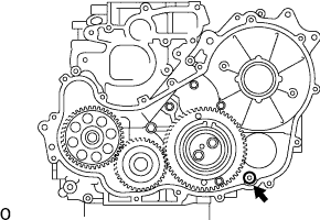
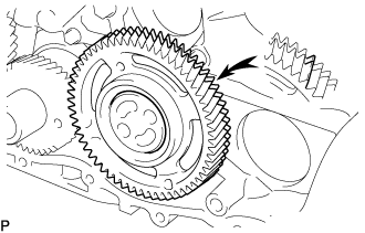
REMOVE CRANKSHAFT TIMING GEAR
-
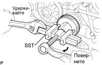
Using SST, remove the crankshaft timing gear.
- SST
- 09950-50013 ( 09951-05010, 09952-05010, 09953-05020, 09954-05011 )
-
-
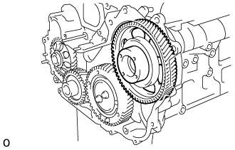
REMOVE IDLE GEAR THRUST PLATE
-
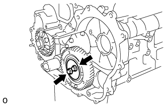
Remove the 2 bolts and thrust plate.
-
-
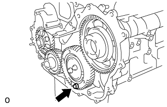
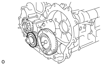
REMOVE IDLE GEAR NO.1
-
Turn the sub gear and align the gear teeth of the idle main gear and sub gear.
-
Remove the idle gear and sub gear.
-
-
REMOVE IDLE GEAR SHAFT NO.1
-
Remove the idle gear shaft.
-
-
REMOVE TIMING GEAR CASE OR TIMING CHAIN CASE OIL SEAL
-
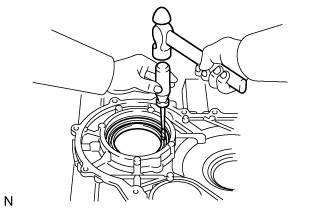
Using a screwdriver and hammer, tap out the oil seal.
-
-
REMOVE TIMING CHAIN OR BELT COVER OIL SEAL
-
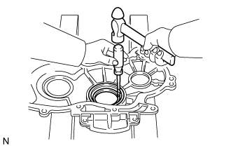
Using a screwdriver and hammer, tap out the oil seal.
-
-
REMOVE OIL PAN SUB-ASSEMBLY
-
Remove the drain plug and gasket.
-
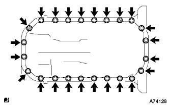
Remove the 22 bolts and 2 nuts.
-
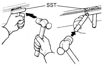
Insert the blade of SST between the oil pan and cylinder block, cut through the applied sealer and remove the oil pan.
Note
-
Do not use SST for the timing belt case side and rear oil seal retainer.
-
Do not damage the oil pan flange.
-
-
-
REMOVE OIL STRAINER SUB-ASSEMBLY
-
Remove the 2 bolts, 2 nuts, oil strainer and gasket.
-
-
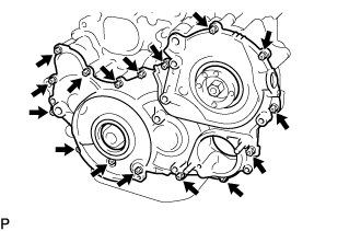
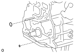
REMOVE TIMING GEAR CASE ASSEMBLY
-
Remove the union bolt and 8 bolts.
-
Pry the gear case in the location shown in the illustration, remove the gear case.
Note
Do not drop the oil pump rotor.
-
Remove the driven rotor and gasket.
-
Remove the stud bolt.
-
Remove the 2 O-rings.
-