LIGHTING SYSTEM Turn Signal Switch Circuit
DESCRIPTION
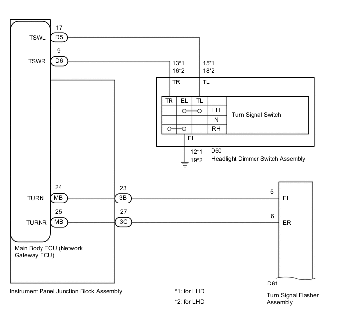
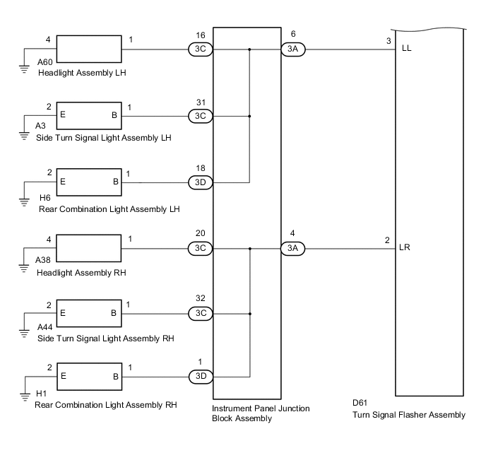
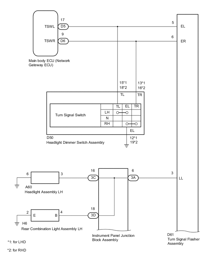
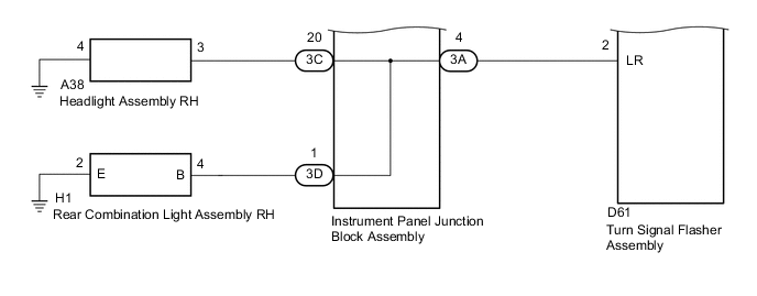
The turn signal flasher assembly receives the main body ECU (network gateway ECU) information and controls the turn signal lights.
WIRING DIAGRAM
-
w/ Side Turn Signal Light
-
w/o Side Turn Signal Light
PROCEDURE
-
CHECK VEHICLE TYPE
-
Check vehicle type.
Result Result Proceed to w/ side turn signal light A w/o side turn signal light B
B 
READ VALUE USING GTS (TURN SIGNAL SWITCH) Click here
A 
-
-
READ VALUE USING GTS (TURN SIGNAL SWITCH)
-
Connect the GTS to the DLC3.
-
Turn the ignition switch to ON.
-
Turn the GTS on.
-
Enter the following menus: Body / Main Body / Data List.
-
Read the Data List according to the display on the GTS.
Main Body Tester Display Measurement Item/Range Normal Condition Diagnostic Note Left Turn Signal Switch Left turn signal switch signal ON or OFF ON: Left turn signal switch on
OFF: Left turn signal switch off
- Right Turn Signal Switch Right turn signal switch signal ON or OFF ON: Right turn signal switch on
OFF: Right turn signal switch off
- OK Normal conditions listed above are displayed.
NG
INSPECT HEADLIGHT DIMMER SWITCH ASSEMBLY Click here
OK
-
-
READ VALUE USING GTS (TURN SIGNAL LIGHT)
-
Connect the GTS to the DLC3.
-
Turn the ignition switch to ON.
-
Turn the GTS on.
-
Enter the following menus: Body / Main Body / Data List.
-
Read the Data List according to the display on the GTS.
Main Body Tester Display Measurement Item/Range Normal Condition Diagnostic Note Left Turn Signal Light Left turn signal light output ON or OFF ON: Left turn signal switch on
OFF: Left turn signal switch off
- Right Turn Signal Light Right turn signal light output ON or OFF ON: Right turn signal switch on
OFF: Right turn signal switch off
- OK Normal conditions listed above are displayed.
OK 
REPLACE MAIN BODY ECU (NETWORK GATEWAY ECU)
NG
-
-
CHECK HARNESS AND CONNECTOR (TURN SIGNAL FLASHER ASSEMBLY - MAIN BODY ECU (NETWORK GATEWAY ECU))
-
Disconnect the 3B and 3C main body ECU (network gateway ECU) connectors.
-
Disconnect the D61 turn signal flasher assembly connector.
-
Measure the resistance according to the value(s) in the table below.
Standard Resistance Tester Connection Condition Specified Condition 3B-23 - D61-5 Always Below 1 Ω 3C-27 - D61-6 Always Below 1 Ω 3B-23 or D61-5 - Body ground Always 10 kΩ or higher 3C-27 or D61-6 - Body ground Always 10 kΩ or higher
NG
REPAIR OR REPLACE HARNESS OR CONNECTOR
OK
-
-
CHECK HARNESS AND CONNECTOR (TURN SIGNAL FLASHER ASSEMBLY - MAIN BODY ECU (NETWORK GATEWAY ECU))
-
Disconnect the 3A main body ECU (network gateway ECU) connectors.
-
Disconnect the D61 turn signal flasher assembly connectors.
-
Measure the resistance according to the value(s) in the table below.
Standard Resistance Tester Connection Condition Specified Condition 3A-4 - D61-2 (LR) Always Below 1 Ω 3A-6 - D61-3 (LL) Always Below 1 Ω 3A-4 or D61-2 (LR) - Body ground Always 10 kΩ or higher 3A-6 or D61-3 (LL) - Body ground Always 10 kΩ or higher
NG
REPAIR OR REPLACE HARNESS OR CONNECTOR
OK
-
-
INSPECT INSTRUMENT PANEL JUNCTION BLOCK ASSEMBLY
-
Disconnect the 3A, 3C and 3D instrument panel junction block assembly connectors.
-
Measure the resistance according to the value(s) in the table below.
Standard Resistance Tester Connection Condition Specified Condition 3A-4 - 3C-20 Always Below 1 Ω 3A-4 - 3C-32 Always Below 1 Ω 3A-4 - 3D-1 Always Below 1 Ω 3A-6 - 3C-16 Always Below 1 Ω 3A-6 - 3C-31 Always Below 1 Ω 3A-6 - 3D-18 Always Below 1 Ω
OK
REPLACE TURN SIGNAL FLASHER ASSEMBLY Click here
NG
REPLACE INSTRUMENT PANEL JUNCTION BLOCK ASSEMBLY
-
-
INSPECT HEADLIGHT DIMMER SWITCH ASSEMBLY
-
Remove the headlight dimmer switch assembly Click here.
-
Inspect the headlight dimmer switch assembly Click here.
NG
REPLACE HEADLIGHT DIMMER SWITCH ASSEMBLY Click here
OK
-
-
CHECK HARNESS AND CONNECTOR (MAIN BODY ECU (NETWORK GATEWAY ECU) - HEADLIGHT DIMMER SWITCH ASSEMBLY)
-
Disconnect the D5 and D6 main body ECU (network gateway ECU) connectors.
-
Disconnect the D50 headlight dimmer switch assembly connectors.
-
for LHD:
-
Measure the resistance according to the value(s) in the table below.
Standard Resistance Tester Connection Condition Specified Condition D5-17 - D50-15(TL) Always Below 1 Ω D6-9 - D50-13(TR) Always Below 1 Ω D50-12(EL) - Body ground Always Below 1 Ω D5-17 or D50-15(TL) - Body ground Always 10 kΩ or higher D6-9 or D50-13(TR) - Body ground Always 10 kΩ or higher
-
-
for RHD:
-
Measure the resistance according to the value(s) in the table below.
Standard Resistance Tester Connection Condition Specified Condition D5-17 - D50-18(TL) Always Below 1 Ω D6-9 - D50-16(TR) Always Below 1 Ω D50-19(EL) - Body ground Always Below 1 Ω D5-17 or D50-18(TL) - Body ground Always 10 kΩ or higher D6-9 or D50-16(TR) - Body ground Always 10 kΩ or higher
-
OK
REPLACE TURN SIGNAL FLASHER ASSEMBLY Click here
NG
REPLACE INSTRUMENT PANEL JUNCTION BLOCK ASSEMBLY
-
-
READ VALUE USING GTS (TURN SIGNAL SWITCH)
-
Connect the GTS to the DLC3.
-
Turn the ignition switch to ON.
-
Turn the GTS on.
-
Enter the following menus: Body / Main Body / Data List.
-
Read the Data List according to the display on the GTS.
Main Body Tester Display Measurement Item/Range Normal Condition Diagnostic Note Left Turn Signal Switch Left turn signal switch signal ON or OFF ON: Left turn signal switch on
OFF: Left turn signal switch off
- Right Turn Signal Switch Right turn signal switch signal ON or OFF ON: Right turn signal switch on
OFF: Right turn signal switch off
- OK Normal conditions listed above are displayed.
NG
CHECK HARNESS AND CONNECTOR (TURN SIGNAL FLASHER ASSEMBLY - INSTRUMENT PANEL JUNCTION BLOCK ASSEMBLY) Click here
OK
-
-
READ VALUE USING GTS (TURN SIGNAL LIGHT)
-
Connect the GTS to the DLC3.
-
Turn the ignition switch to ON.
-
Turn the GTS on.
-
Enter the following menus: Body / Main Body / Data List.
-
Read the Data List according to the display on the GTS.
Main Body Tester Display Measurement Item/Range Normal Condition Diagnostic Note Left Turn Signal Light Left turn signal light output ON or OFF ON: Left turn signal switch on
OFF: Left turn signal switch off
- Right Turn Signal Light Right turn signal light output ON or OFF ON: Right turn signal switch on
OFF: Right turn signal switch off
- OK Normal conditions listed above are displayed.
OK
REPLACE MAIN BODY ECU (NETWORK GATEWAY ECU)
NG
-
-
INSPECT HEADLIGHT DIMMER SWITCH
-
Remove the headlight dimmer switch assembly Click here.
-
Inspect the headlight dimmer switch assembly Click here.
NG
REPLACE HEADLIGHT DIMMER SWITCH ASSEMBLY Click here
OK
-
-
CHECK HARNESS AND CONNECTOR (TURN SIGNAL FLASHER ASSEMBLY - HEADLIGHT DIMMER SWITCH ASSEMBLY)
-
Disconnect the D61 turn signal flasher assembly connectors.
-
Disconnect the D50 headlight dimmer switch assembly connectors.
-
for LHD:
-
Measure the resistance according to the value(s) in the table below.
Standard Resistance Tester Connection Condition Specified Condition D50-15(TL) - D61-5(EL) Always Below 1 Ω D50-13(TR) - D61-6(ER) Always Below 1 Ω D50-12(EL) - Body ground Always Below 1 Ω D50-15(TL) or D61-5(EL) - Body ground Always 10 kΩ or higher D50-13(TR) or D61-6(ER) - Body ground Always 10 kΩ or higher
-
-
for RHD:
-
Measure the resistance according to the value(s) in the table below.
Standard Resistance Tester Connection Condition Specified Condition D50-18(TL) - D61-5(EL) Always Below 1 Ω D50-16(TR) - D61-6(ER) Always Below 1 Ω D50-19(EL) - Body ground Always Below 1 Ω D50-18(TL) or D61-5(EL) - Body ground Always 10 kΩ or higher D50-16(TR) or D61-6(ER) - Body ground Always 10 kΩ or higher
-
OK
REPLACE TURN SIGNAL FLASHER ASSEMBLY Click here
NG
REPAIR OR REPLACE HARNESS OR CONNECTOR
-
-
CHECK HARNESS AND CONNECTOR (TURN SIGNAL FLASHER ASSEMBLY - INSTRUMENT PANEL JUNCTION BLOCK ASSEMBLY)
-
Disconnect the 3A instrument panel junction block assembly connectors.
-
Disconnect the D61 turn signal flasher assembly connectors.
-
Measure the resistance according to the value(s) in the table below.
Standard Resistance Tester Connection Condition Specified Condition 3A-4 - D61-2 (LR) Always Below 1 Ω 3A-6 - D61-3 (LL) Always Below 1 Ω 3A-4 or D61-2 (LR) - Body ground Always 10 kΩ or higher 3A-6 or D61-3 (LL) - Body ground Always 10 kΩ or higher
NG
REPAIR OR REPLACE HARNESS OR CONNECTOR
OK
-
-
INSPECT INSTRUMENT PANEL JUNCTION BLOCK ASSEMBLY
-
Disconnect the 3A, 3C and 3D instrument panel junction block assembly connectors.
-
Measure the resistance according to the value(s) in the table below.
Standard Resistance Tester Connection Condition Specified Condition 3A-4 - 3C-20 Always Below 1 Ω 3A-4 - 3D-1 Always Below 1 Ω 3A-6 - 3C-16 Always Below 1 Ω 3A-4 - 3D-18 Always Below 1 Ω
OK
REPLACE TURN SIGNAL FLASHER ASSEMBLY Click here
NG
REPLACE INSTRUMENT PANEL JUNCTION BLOCK ASSEMBLY
-