LIGHTING SYSTEM Taillight Relay Circuit
DESCRIPTION
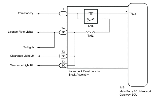
The main body ECU (network gateway ECU) receives headlight dimmer switch assembly information signals, and illuminates the clearance lights, taillights and license plate lights.
WIRING DIAGRAM
CAUTION / NOTICE / HINT
Tech Tips
Inspect the fuses and bulbs for circuits related to this system before performing the following inspection procedure.
PROCEDURE
-
PERFORM ACTIVE TEST USING GTS (TAIL RELAY)
-
Connect the GTS to the DLC3.
-
Turn the ignition switch to ON.
-
Turn the GTS on.
-
Enter the following menus: Body Electrical / Main Body / Active Test
-
Check that the relay operates.
Main Body Tester Display Test Part Control Range Diagnostic Note Taillight Relay Taillight relay ON/OFF - OK Taillight relay operates (taillights illuminate). Result Result Proceed to NG A OK B
B 
REPLACE MAIN BODY ECU (NETWORK GATEWAY ECU) Click here
A 
-
-
CHECK HARNESS AND CONNECTOR (BATTERY - INSTRUMENT PANEL JUNCTION BLOCK)
-
Disconnect the 3E instrument panel junction block assembly connector.
-
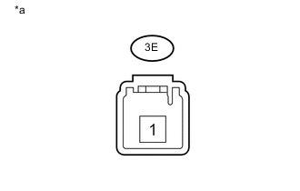
Text in Illustration *a Component without harness connected
(Instrument Panel Junction Block Assembly)
Measure the voltage according to the value(s) in the table below.
Standard Voltage Tester Connection Condition Specified Condition 3E-1 - Body ground Always 11 to 14 V
NG
REPAIR OR REPLACE HARNESS OR CONNECTOR
OK
-
-
INSPECT INSTRUMENT PANEL JUNCTION BLOCK ASSEMBLY
-
Remove the instrument panel junction block assembly Click here.
-
Remove the main body ECU (network gateway ECU) from the instrument panel junction block assembly.
-
Measure the voltage according to the value(s) in the table below.
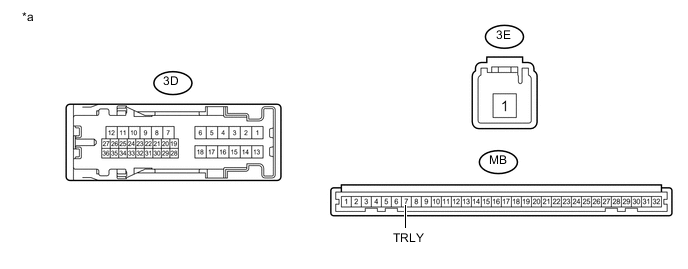
Text in Illustration *a Component without harness connected
(Instrument Panel Junction Block Assembly)
- - Standard Voltage Tester Connection Condition Specified Condition 3C-12 - Battery negative (-) terminal Connect a positive (+) lead from the battery → 3E-1
Connect a negative (-) lead from the battery → MB-7 (TRLY)
11 to 14 V 3C-13 - Battery negative (-) terminal Connect a positive (+) lead from the battery → 3E-1
Connect a negative (-) lead from the battery → MB-7 (TRLY)
11 to 14 V 3D-24 - Battery negative (-) terminal Connect a positive (+) lead from the battery → 3E-1
Connect a negative (-) lead from the battery → MB-7 (TRLY)
11 to 14 V -
Measure the resistance according to the value(s) in the table below.
Standard Resistance Tester Connection Condition Specified Condition 3E-1 - 3C-12 Always 10 kΩ or higher 3E-1 - 3C-13 Always 10 kΩ or higher 3E-1 - 3D-24 Always 10 kΩ or higher
OK
PROCEED TO NEXT SUSPECTED AREA SHOWN IN PROBLEM SYMPTOMS TABLE Click here
NG
REPLACE INSTRUMENT PANEL JUNCTION BLOCK ASSEMBLY Click here
-