LANE DEPARTURE ALERT SYSTEM Lane Departure Alert System Switch Circuit
| DTC Code | DTC Name |
|---|---|
| Lane Departure Alert System Switch Circuit |
DESCRIPTION
The lane departure alert system and lane departure alert indicator light (green) in the combination meter assembly turn on or off when the lane departure alert switch is pressed.
WIRING DIAGRAM
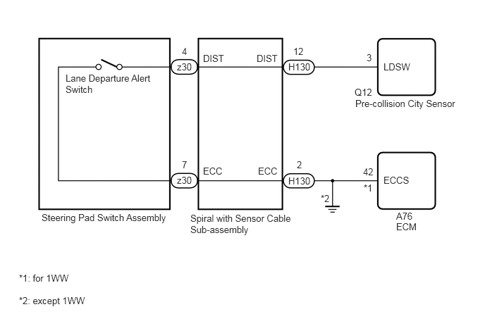
PROCEDURE
INSPECT STEERING PAD SWITCH ASSEMBLY
Remove the steering pad switch assembly (Click here).
Inspect the steering pad switch assembly (Click here).
INSPECT SPIRAL CABLE WITH SENSOR SUB-ASSEMBLY
Remove the spiral cable with sensor sub-assembly (Click here).
Inspect the spiral cable with sensor sub-assembly (Click here).
CHECK HARNESS AND CONNECTOR
Disconnect the H130 spiral cable with sensor sub-assembly connector.
Disconnect the Q12 pre-collision city sensor connector.
for 1WW:
Disconnect the A76 ECM connector.
except 1WW:
Measure the resistance according to the value(s) in the table below.
Standard Resistance
Tester Connection
Condition
Specified Condition
H130-12 (DIST) - Q12-3 (LDSW)
Always
Below 1 Ω
H130-12 (DIST) or Q12-3 (LDSW) - Body ground
Always
10 kΩ or higher
H130-2 (ECC) - Body ground
Always
Below 1 Ω
for 1WW:
Measure the resistance according to the value(s) in the table below.
Standard Resistance
Tester Connection
Condition
Specified Condition
H130-12 (DIST) - Q12-3 (LDSW)
Always
Below 1 Ω
H130-12 (DIST) or Q12-3 (LDSW) - Body ground
Always
10 kΩ or higher
H130-2 (ECC) - A76-42 (ECCS)
Always
Below 1 Ω
REPAIR OR REPLACE HARNESS OR CONNECTOR