AIR CONDITIONING SYSTEM, Diagnostic DTC:B1443/43
| DTC Code | DTC Name |
|---|---|
| B1443/43 | Air Outlet Damper Control Servo Motor Circuit |
DESCRIPTION
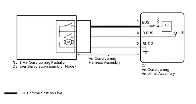
The No. 1 air conditioning radiator damper servo sub-assembly (mode) sends pulse signals to inform the air conditioning amplifier assembly of the damper position. The air conditioning amplifier assembly activates the motor (normal, reverse) based on the signals to move the No. 1 air conditioning radiator damper servo sub-assembly (mode) to any position, which controls the air outlet switching.
DTC No. |
Detection Item |
DTC Detection Condition |
Trouble Area |
Memory |
Note |
|---|---|---|---|---|---|
B1443/43 |
Air Outlet Damper Control Servo Motor Circuit |
Air outlet damper position sensor value does not change even if air conditioning amplifier assembly operates No. 1 air conditioning radiator damper servo sub-assembly (mode) |
|
Memorized (30 seconds or more) |
- |
The air conditioning amplifier assembly stores the DTC of the respective malfunction if it has occurred for the period of time indicated in the parentheses.
WIRING DIAGRAM
CAUTION / NOTICE / HINT
When the servo motor or air conditioning amplifier assembly is replaced, be sure to perform servo motor initialization.
When DTC B1443/43 and DTC B1497/97 are output simultaneously, first perform troubleshooting for DTC B1497/97.
Confirm that no mechanical problem is present because this diagnostic code can be output when either a damper link or the damper is mechanically locked.
PROCEDURE
READ VALUE USING GTS (AIR OUTLET SERVO PULSE [D], AIR OUTLET SERVO ACTU PULSE[D])
Connect the GTS to the DLC3.
Turn the power switch on (IG).
Turn the GTS on.
Operate the MODE switch.
Enter the following menus: Body Electrical / Air Conditioner / Data List.
Check the value(s) by referring to the table below.
Body Electrical > Air Conditioner > Data List
Tester Display
Measurement Item
Range
Normal Condition
Diagnostic Note
Air Outlet Servo Pulse (D)
No. 1 air conditioning radiator damper servo sub-assembly (mode) target pulse
Min.: 0
Max.: 255
FACE: 47 (pulse)
B/L: 37 (pulse)
FOOT: 17 (pulse)
FOOT/DEF: 9 (pulse)
DEF: 5 (pulse)
Displayed between 5 and 47 pulse
No. 1 air conditioning radiator damper servo sub-assembly (mode) system malfunction
Air Outlet Servo Actu Pulse(D)
No. 1 air conditioning radiator damper servo sub-assembly (mode) actual pulse
Min.: 0
Max.: 255
FACE: 47 (pulse)
B/L: 37 (pulse)
FOOT: 17 (pulse)
FOOT/DEF: 9 (pulse)
DEF: 5 (pulse)
Displayed between 5 and 47 pulse
No. 1 air conditioning radiator damper servo sub-assembly (mode) system malfunction
Body Electrical > Air Conditioner > Data List
Tester Display
Air Outlet Servo Pulse (D)
Air Outlet Servo Actu Pulse(D)
OK
When the mode switch is turned, the actual pulse changes following the target pulse.
Result
Result
Proceed to
Target pulse and actual pulse do not change
A
Target pulse changes but actual pulse does not change
B
Actual pulse changes following the target pulse (When troubleshooting according to the DTC)
C
Actual pulse changes following the target pulse (When troubleshooting according to Problem Symptoms Table)
D
C CHECK FOR DTCClick here
CHECK NO. 1 AIR CONDITIONING RADIATOR DAMPER SERVO SUB-ASSEMBLY (MODE)
Replace the No. 1 air conditioning radiator damper servo sub-assembly (mode).
Tip:Since the servo motor cannot be inspected while it is removed from the vehicle, replace the servo motor with a new or known good one and check that the condition returns to normal.
Clear the DTCs.
Body Electrical > Air Conditioner > Clear DTCs
Check for DTCs.
Body Electrical > Air Conditioner > Trouble Codes
OK
DTC B1443/43 is not output.
Result
Proceed to
OK
NG
OK END (NO. 1 AIR CONDITIONING RADIATOR DAMPER SERVO SUB-ASSEMBLY [MODE] WAS DEFECTIVE)
CHECK AIR CONDITIONING HARNESS ASSEMBLY
Replace the air conditioning harness assembly.
Tip:Since the air conditioning harness assembly cannot be inspected while it is removed from the vehicle, replace the air conditioning harness assembly with a new or known good one and check that the condition returns to normal.
Clear the DTCs.
Body Electrical > Air Conditioner > Clear DTCs
Check for DTCs.
Body Electrical > Air Conditioner > Trouble Codes
OK
DTC B1443/43 is not output.
Result
Proceed to
OK
NG
OK END (AIR CONDITIONING HARNESS ASSEMBLY WAS DEFECTIVE)
CHECK FOR DTC
Clear the DTCs.
Body Electrical > Air Conditioner > Clear DTCs
Check for DTCs.
Body Electrical > Air Conditioner > Trouble Codes
OK
DTC B1443/43 is not output.
Result
Proceed to
OK
NG