AIR CONDITIONING SYSTEM Air Conditioning Control Panel Circuit
| DTC Code | DTC Name |
|---|---|
| Air Conditioning Control Panel Circuit |
DESCRIPTION
w/ Navigation System:
This circuit consists of the display and navigation module display and air conditioning amplifier assembly. When the display and navigation module display is operated, signals are transmitted to the air conditioning amplifier assembly through the CAN communication system.
If the CAN communication system malfunctions, the air conditioning amplifier assembly does not operate when the display and navigation module display is operated.
w/o Navigation System:
This circuit consists of the air conditioning control assembly, accessory meter assembly and air conditioning amplifier assembly. When the air conditioning control assembly is operated, signals are transmitted to the air conditioning amplifier assembly through the LIN communication system.
If the LIN communication system malfunctions, the air conditioning amplifier assembly does not operate when the air conditioning control assembly is operated.
WIRING DIAGRAM
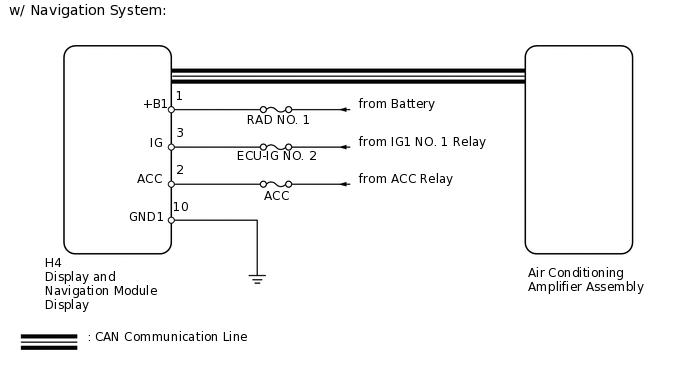
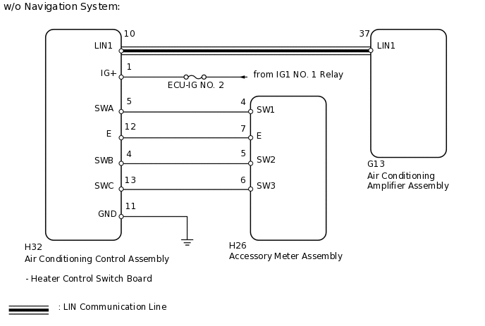
CAUTION / NOTICE / HINT
Inspect the fuses for circuits related to this system before performing the following inspection procedure.
Before performing the inspection, check that there are no problems related to the CAN communication system. (w/ Navigation System)
PROCEDURE
CHECK VEHICLE TYPE
Check vehicle type.
Result
Result
Proceed to
w/ Navigation system
A
w/o Navigation system
B
B CHECK HARNESS AND CONNECTOR (AIR CONDITIONING CONTROL - AIR CONDITIONING AMPLIFIER)Click here
CHECK HARNESS AND CONNECTOR (SPLAY AND NAVIGATION MODULE DISPLAY - BATTERY AND BODY GROUND)
-
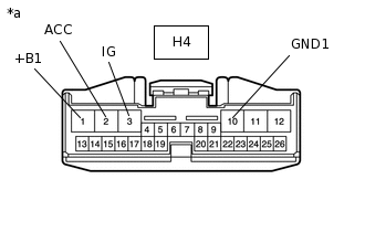
*a
Front view of wire harness connector
(to Display and Navigation Module Display)
Disconnect the H4 display connector.
Measure the voltage according to the value(s) in the table below.
Standard Voltage
Tester Connection
Switch Condition
Specified Condition
H4-1 (+B1) - H4-10 (GND1)
Always
11 to 14 V
H4-3 (IG) - H4-10 (GND1)
Engine switch off
Below 1 V
H4-3 (IG) - H4-10 (GND1)
Engine switch on (IG)
11 to 14 V
H4-2 (ACC) - H4-10 (GND1)
Engine switch on (ACC)
11 to 14 V
Measure the resistance according to the value(s) in the table below.
Standard Resistance
Tester Connection
Condition
Specified Condition
H4-10 (GND1) - Body ground
Always
Below 1 Ω
Result
Result
OK
NG
NG REPAIR OR REPLACE HARNESS OR CONNECTOR
-
REPLACE DISPLAY AND NAVIGATION MODULE DISPLAY
Replace the display and navigation module display with a new or normally functioning one
Operate the display and navigation module display to check that it functions properly.
OK
Display and navigation module display operates normally.
Result
Result
OK
NG
OK END (DISPLAY AND NAVIGATION MODULE DISPLAY IS FAULTY)
CHECK HARNESS AND CONNECTOR (AIR CONDITIONING CONTROL - AIR CONDITIONING AMPLIFIER)
Disconnect the G13 amplifier connector.
Disconnect the H32 control connector.
Measure the resistance according to the value(s) in the table below.
Standard Resistance
Tester Connection
Condition
Specified Condition
H32-10 (LIN1) - G13-37 (LIN1)
Always
Below 1 Ω
H32-10 (LIN1) - Body ground
Always
10 kΩ or higher
Result
Result
OK
NG
NG REPAIR OR REPLACE HARNESS OR CONNECTOR
CHECK HARNESS AND CONNECTOR (AIR CONDITIONING CONTROL - BATTERY AND BODY GROUND)
-
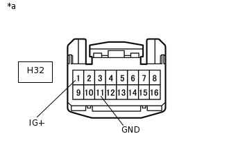
*a
Front view of wire harness connector
(to Air Conditioning Control Assembly)
Disconnect the H32 control connector.
Measure the voltage according to the value(s) in the table below.
Standard Voltage
Tester Connection
Switch Condition
Specified Condition
H32-1 (IG+) - H32-11 (GND)
Engine switch off
Below 1 V
H32-1 (IG+) - H32-11 (GND)
Engine switch on (IG)
11 to 14 V
Measure the resistance according to the value(s) in the table below.
Standard Resistance
Tester Connection
Condition
Specified Condition
H32-11 (GND) - Body ground
Always
Below 1 Ω
Result
Result
OK
NG
NG REPAIR OR REPLACE HARNESS OR CONNECTOR
-
CHECK HARNESS AND CONNECTOR (AIR CONDITIONING CONTROL - ACCESSORY METER)
Disconnect the H32 control connector.
Disconnect the H26 meter connector.
Measure the resistance according to the value(s) in the table below.
Standard Resistance
Tester Connection
Condition
Specified Condition
H32-5 (SWA) - H26-4 (SW1)
Always
Below 1 Ω
H32-12 (E) - H26-7 (E)
Always
Below 1 Ω
H32-4 (SWB) - H26-5 (SW2)
Always
Below 1 Ω
H32-13 (SWC) - H26-6 (SW3)
Always
Below 1 Ω
H32-5 (SWA) - Body ground
Always
10 kΩ or higher
H32-12 (E) - Body ground
Always
10 kΩ or higher
H32-4 (SWB) - Body ground
Always
10 kΩ or higher
H32-13 (SWC) - Body ground
Always
10 kΩ or higher
Result
Result
OK
NG
NG REPAIR OR REPLACE HARNESS OR CONNECTOR
REPLACE HEATER CONTROL SWITCH BOARD
Replace the heater control switch board with a new or normally functioning one
Operate the air conditioning control assembly to check that it functions properly.
OK
Air conditioning control assembly operates normally.
Result
Result
OK
NG
OK END (HEATER CONTROL SWITCH BOARD IS FAULTY)
REPLACE ACCESSORY METER ASSEMBLY
Replace the accessory meter assembly with a new or normally functioning one
Operate the accessory meter assembly to check that it functions properly.
OK
Accessory meter assembly operates normally.
Result
Result
OK
NG
OK END (ACCESSORY METER ASSEMBLY IS FAULTY)