AIR CONDITIONING SYSTEM(for Manual Air Conditioning System) Blower Motor Circuit
| DTC Code | DTC Name |
|---|---|
| Blower Motor Circuit |
DESCRIPTION
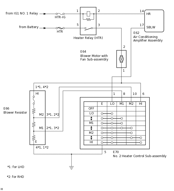
When the No. 2 heater control sub-assembly is operated, the heater relay will turn on to allow current to flow to the blower motor and then the motor will start rotating. Operating the No. 2 heater control sub-assembly switches the current flow between the blower resistor and body ground, thus, shifting the rotation speed of the blower motor with fan sub-assembly.
WIRING DIAGRAM
CAUTION / NOTICE / HINT
Inspect the fuses for circuits related to this system before performing the following procedure.
PROCEDURE
INSPECT HEATER RELAY (HTR)
-
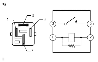
*a
Component without harness connected
(Heater Relay (HTR))
Remove the heater relay (HTR).
Measure the resistance according to the value(s) in the table below.
Standard Resistance
Tester Connection
Condition
Specified Condition
3 - 5
Battery voltage is not applied between terminals 1 and 2
10 kΩ or higher
3 - 5
Battery voltage is applied between terminals 1 and 2
Below 1 Ω
Result
Proceed to
OK
NG
NG REPLACE HEATER RELAY (HTR)
-
INSPECT BLOWER MOTOR WITH FAN SUB-ASSEMBLY
Disconnect the E64 blower motor with fan sub-assembly connector.
-
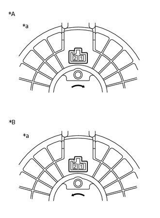
*A
for LHD
*B
for RHD
*a
Component without harness connected
(Blower Motor with Fan Sub-assembly)
Connect a positive (+) lead from the battery to terminal 2 and a negative (-) lead to terminal 1, and check that the motor operates.
OK
The blower motor with fan sub-assembly operates smoothly.
Result
Proceed to
OK
NG
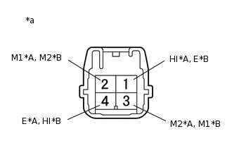
INSPECT BLOWER RESISTOR
-
*A
for LHD
*B
for RHD
*a
Component without harness connected
(Blower Resistor)
Remove the blower resistor.
Measure the resistance according to the value(s) in the table below.
Standard Resistance
for LHD
Tester Connection
Condition
Specified Condition
4 (E) - 1 (HI)
Always
3.12 to 3.60 Ω
2 (M1) - 1 (HI)
Always
1.45 to 1.67 Ω
3 (M2) - 1 (HI)
Always
0.52 to 0.60 Ω
Standard Resistance
for RHD
Tester Connection
Condition
Specified Condition
1 (E) - 4 (HI)
Always
3.12 to 3.60 Ω
3 (M1) - 4 (HI)
Always
1.45 to 1.67 Ω
2 (M2) - 4 (HI)
Always
0.52 to 0.60 Ω
Result
Proceed to
OK
NG
-
INSPECT NO. 2 HEATER CONTROL SUB-ASSEMBLY
-
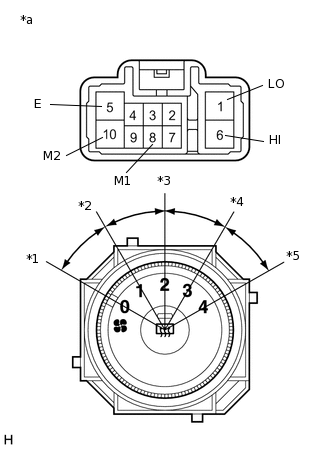
*a
Component without harness connected
(No. 2 Heater Control Sub-assembly)
*1
Blower Switch OFF Position
*2
Blower Switch LO Position
*3
Blower Switch M1 Position
*4
Blower Switch M2 Position
*5
Blower Switch HI Position
Remove the No. 2 heater control sub-assembly.
Measure the resistance according to the value(s) in the table below.
Standard Resistance
Tester Connection
Condition
Specified Condition
1 (LO), 6 (HI), 8 (M1), 10 (M2) - 5 (E)
Blower switch: OFF
10 kΩ or higher
1 (LO) - 5 (E)
Blower switch: LO
Below 1 Ω
1 (LO), 8 (M1) - 5 (E)
Blower switch: LO - M1
Below 1 Ω
1 (LO), 8 (M1) - 5 (E)
Blower switch: M1
Below 1 Ω
1 (LO), 8 (M1), 10 (M2) - 5 (E)
Blower switch: M1 - M2
Below 1 Ω
1 (LO), 10 (M2) - 5 (E)
Blower switch: M2
Below 1 Ω
1 (LO), 10 (M2), 6 (HI) - 5 (E)
Blower switch: M2 - HI
Below 1 Ω
1 (LO), 6 (HI) - 5 (E)
Blower switch: HI
Below 1 Ω
Result
Proceed to
OK
NG
-
CHECK HARNESS AND CONNECTOR (AIR CONDITIONING AMPLIFIER ASSEMBLY - HEATER RELAY (HTR))
Measure the resistance according to the value(s) in the table below.
Standard Resistance
Tester Connection
Condition
Specified Condition
Heater relay terminal 2 - E62-14 (HR)
Always
Below 1 Ω
Heater relay terminal 2 - Body ground
Always
10 kΩ or higher
Result
Proceed to
OK
NG
NG REPAIR OR REPLACE HARNESS OR CONNECTOR
CHECK HARNESS AND CONNECTOR (NO. 2 HEATER CONTROL SUB-ASSEMBLY - AIR CONDITIONING AMPLIFIER ASSEMBLY)
Measure the resistance according to the value(s) in the table below.
Standard Resistance
Tester Connection
Condition
Specified Condition
E62-17 (SBLW) - E70-1 (LO)
Always
Below 1 Ω
E62-17 (SBLW) - Body ground
Always
10 kΩ or higher
Result
Proceed to
OK
NG
NG REPAIR OR REPLACE HARNESS OR CONNECTOR
CHECK HARNESS AND CONNECTOR (BLOWER RESISTOR - NO. 2 HEATER CONTROL SUB-ASSEMBLY)
Measure the resistance according to the value(s) in the table below.
Standard Resistance
for LHD
Tester Connection
Condition
Specified Condition
E66-1 (HI) - E70-6 (HI)
Always
Below 1 Ω
E66-3 (M2) - E70-10 (M2)
Always
Below 1 Ω
E66-2 (M1) - E70-8 (M1)
Always
Below 1 Ω
E66-4 (E) - Body ground
Always
Below 1 Ω
E70-5 (E) - Body ground
Always
Below 1 Ω
E66-1 (HI) - Body ground
Always
10 kΩ or higher
E66-3 (M2) - Body ground
Always
10 kΩ or higher
E66-2 (M1) - Body ground
Always
10 kΩ or higher
Standard Resistance
for RHD
Tester Connection
Condition
Specified Condition
E66-4 (HI) - E70-6 (HI)
Always
Below 1 Ω
E66-2 (M2) - E70-10 (M2)
Always
Below 1 Ω
E66-3 (M1) - E70-8 (M1)
Always
Below 1 Ω
E66-1 (E) - Body ground
Always
Below 1 Ω
E70-5 (E) - Body ground
Always
Below 1 Ω
E66-4 (HI) - Body ground
Always
10 kΩ or higher
E66-2 (M2) - Body ground
Always
10 kΩ or higher
E66-3 (M1) - Body ground
Always
10 kΩ or higher
Result
Proceed to
OK
NG
NG REPAIR OR REPLACE HARNESS OR CONNECTOR
CHECK HARNESS AND CONNECTOR (BLOWER MOTOR WITH FAN SUB-ASSEMBLY - NO. 2 HEATER CONTROL SUB-ASSEMBLY)
Measure the resistance according to the value(s) in the table below.
Standard Resistance
Tester Connection
Condition
Specified Condition
E64-1 - E70-6 (HI)
Always
Below 1 Ω
E64-1 - Body ground
Always
10 kΩ or higher
Result
Proceed to
OK
NG
NG REPAIR OR REPLACE HARNESS OR CONNECTOR
CHECK HARNESS AND CONNECTOR (BLOWER MOTOR WITH FAN SUB-ASSEMBLY - HEATER RELAY (HTR))
Measure the resistance according to the value(s) in the table below.
Standard Resistance
Tester Connection
Condition
Specified Condition
Heater relay terminal 3 - E64-2
Always
Below 1 Ω
Heater relay terminal 3 - Body ground
Always
10 kΩ or higher
Result
Proceed to
OK
NG
NG REPAIR OR REPLACE HARNESS OR CONNECTOR