POWER WINDOW CONTROL SYSTEM Power Windows do not Operate Using All Window Switch
| DTC Code | DTC Name |
|---|---|
| Power Windows do not Operate Using All Window Switch |
DESCRIPTION
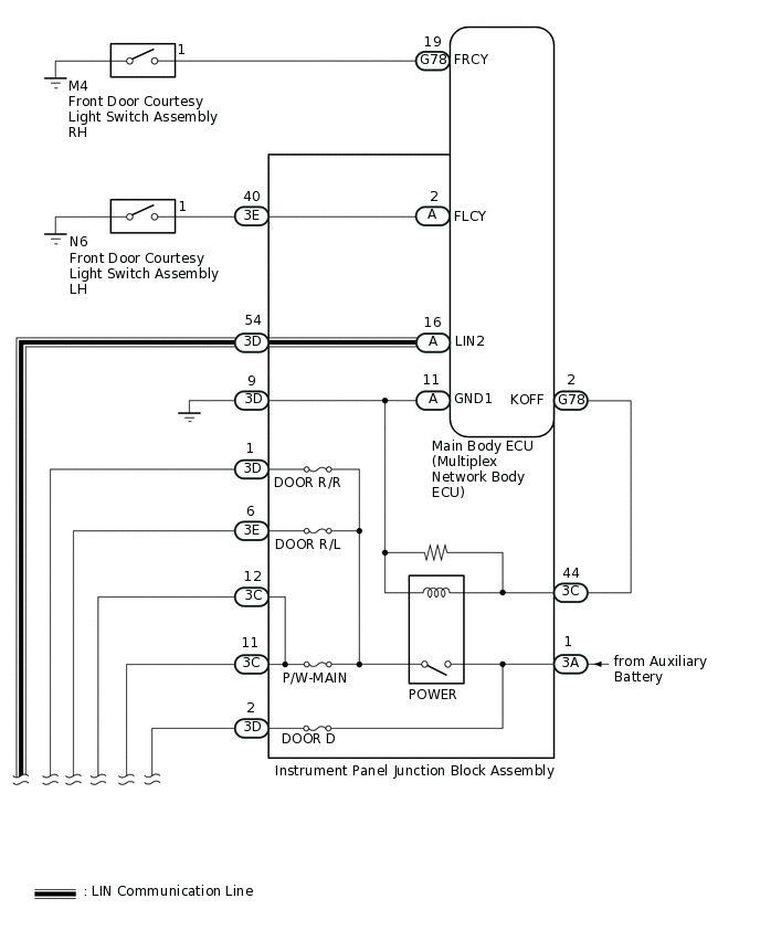
The power windows operate by using the power window regulator master switch assembly, power window regulator switch assembly, rear power window regulator switch assembly LH or rear power window regulator switch assembly RH.
The power window regulator master switch assembly, power window regulator switch assembly, rear power window regulator switch assembly LH and rear power window regulator switch assembly RH connect the same power supply and ground lines.
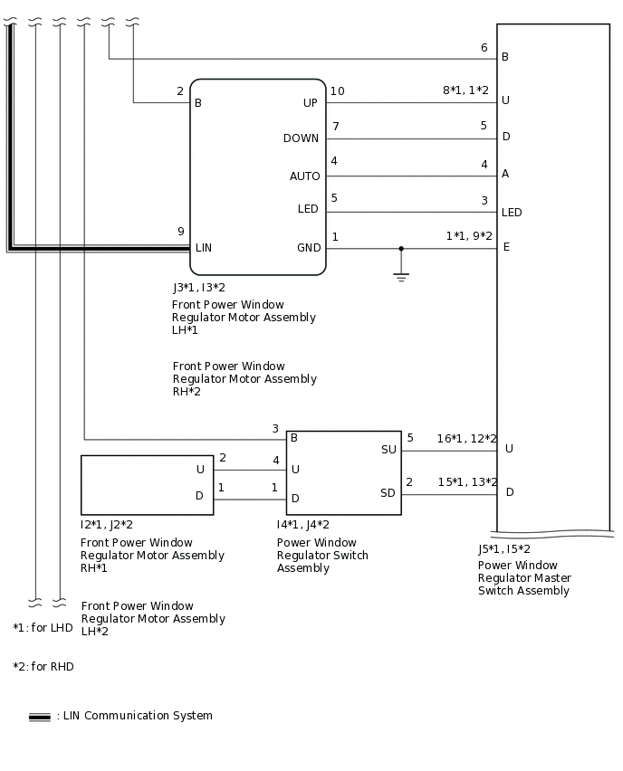
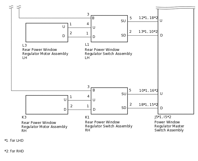
WIRING DIAGRAM
CAUTION / NOTICE / HINT
Inspect the fuses for circuits related to this system before performing the following procedure.
When replacing the main body ECU (multiplex network body ECU), make sure to replace it with a new one.
PROCEDURE
CHECK MAIN BODY ECU (MULTIPLEX NETWORK BODY ECU)
-
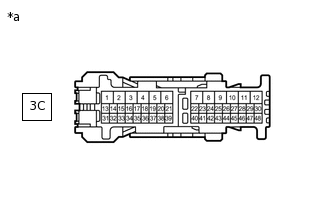
*a
Front vie of wire harness connector
(to Instrument Panel Junction Block Assembly)
Disconnect the instrument panel junction block assembly connector.
Measure the voltage according to the value(s) in the table below.
Standard Voltage
Tester Connection
Switch Condition
Specified Condition
3C-44 - Body ground
Power switch on (IG)
11 to 14 V
Power switch off
Below 1 V
Result
Proceed to
OK
NG
NG CHECK HARNESS AND CONNECTOR (MAIN BODY ECU - INSTRUMENT PANEL JUNCTION BLOCK ASSEMBLY AND BODY GROUND)Click here
-
CHECK HARNESS AND CONNECTOR (MAIN BODY ECU - AUXILIARY BATTERY AND BODY GROUND)
-
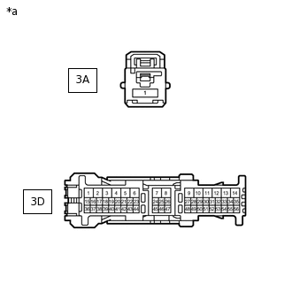
*a
Front vie of wire harness connector
(to Instrument Panel Junction Block Assembly)
Disconnect the instrument panel junction block assembly connectors.
Measure the resistance according to the value(s) in the table below.
Standard Resistance
Tester Connection
Condition
Specified Condition
3D-9 - Body ground
Always
Below 1 Ω
Measure the voltage according to the value(s) in the table below.
Standard Voltage
Tester Connection
Condition
Specified Condition
3A-1 - Body ground
Always
11 to 14 V
Result
Proceed to
OK
NG
NG REPAIR OR REPLACE HARNESS OR CONNECTOR
-
CHECK HARNESS AND CONNECTOR (POWER WINDOW MASTER SWITCH ASSEMBLY - AUXILIARY BATTERY AND BODY GROUND)
-
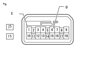
*a
Front view of wire harness connector
(to Power Window Regulator Master Switch Assembly)
Disconnect the power window regulator master switch assembly connector.
Measure the resistance according to the value(s) in the table below.
Standard Resistance
Table 1. for LHD: Tester Connection
Condition
Specified Condition
J5-1(E) - Body ground
Always
Below 1 Ω
Standard Resistance
Table 2. for RHD: Tester Connection
Condition
Specified Condition
I5-1(E) - Body ground
Always
Below 1 Ω
Measure the voltage according to the value(s) in the table below.
Standard Voltage
Table 3. for LHD: Tester Connection
Switch Condition
Specified Condition
J5-6 (B) - Body ground
Power switch on (IG)
11 to 14 V
Power switch off
Below 1 V
Standard Voltage
Table 4. for RHD: Tester Connection
Switch Condition
Specified Condition
I5-6 (B) - Body ground
Power switch on (IG)
11 to 14 V
Power switch off
Below 1 V
Result
Proceed to
OK
NG
NG CHECK HARNESS AND CONNECTOR (INSTRUMENT PANEL JUNCTION BLOCK ASSEMBLY - POWER WINDOW REGULATOR MASTER SWITCH ASSEMBLY AND BODY GROUND)Click here
-
INSPECT POWER WINDOW REGULATOR MASTER SWITCH ASSEMBLY
Remove the power window regulator master switch assembly.
Inspect the power window regulator master switch assembly.
Result
Proceed to
OK
NG
CHECK HARNESS AND CONNECTOR (INSTRUMENT PANEL JUNCTION BLOCK ASSEMBLY - POWER WINDOW REGULATOR MASTER SWITCH ASSEMBLY AND BODY GROUND)
Disconnect the 3C instrument panel junction block assembly connector.
Disconnect the J5 power window regulator master switch assembly connector.
Measure the resistance according to the value(s) in the table below.
Standard Resistance
Tester Connection
Condition
Specified Condition
3C-11 - J5-6 (B)
Always
Below 1 Ω
J5-1 (E) - Body ground
Always
Below 1 Ω
3C-11 or J5-6 (B) - Body ground
Always
10 kΩ or higher
Result
Proceed to
OK
NG
NG REPAIR OR REPLACE HARNESS OR CONNECTOR
CHECK HARNESS AND CONNECTOR (MAIN BODY ECU - INSTRUMENT PANEL JUNCTION BLOCK ASSEMBLY AND BODY GROUND)
Disconnect the G78 main body ECU (multiplex network body ECU) connector.
Disconnect the 3C and 3D instrument panel junction block assembly connectors.
Measure the resistance according to the value(s) in the table below.
Standard Resistance
Tester Connection
Condition
Specified Condition
G78-2 (KOFF) - 3C-44
Always
Below 1 Ω
3D-9 - Body ground
Always
Below 1 Ω
G78-2 (KOFF) or 3C-44 - Body ground
Always
10 kΩ or higher
Result
Proceed to
OK
NG
NG REPAIR OR REPLACE HARNESS OR CONNECTOR