ELECTRONICALLY CONTROLLED BRAKE SYSTEM, Diagnostic DTC:C1247/47,C1346/71 and C1392/48
| DTC Code | DTC Name |
|---|---|
| C1247/47 | Stroke Sensor Malfunction |
| C1346/71 | Stroke Sensor Zero Point Learning Malfunction (Test Mode DTC) |
| C1392/48 | Stroke Sensor Zero Point Calibration Undone |
DESCRIPTION
The brake pedal stroke sensor assembly sends a signal about the pedal stroke to the skid control ECU (brake booster with master cylinder assembly).
DTC C1346/71 will be cleared when the brake pedal stroke sensor assembly sends a brake pedal stroke sensor assembly signal or when Test Mode ends. DTC C1346/71 is output only in Test Mode.
DTC No. |
Detection Item |
INF Code |
DTC Detection Condition |
Trouble Area |
Note |
|---|---|---|---|---|---|
C1247/47 |
Stroke Sensor Malfunction |
211 212 213 214 215 216 217 218 219 220 221 222 223 |
|
|
Electronically controlled brake system DTC |
C1346/71 |
Stroke Sensor Zero Point Learning Malfunction (Test Mode DTC) |
- |
Detected only during Test Mode. |
|
Electronically controlled brake system Test Mode DTC |
C1392/48 |
Stroke Sensor Zero Point Calibration Undone |
- |
Zero point calibration of brake pedal stroke sensor assembly is unfinished. |
|
Electronically controlled brake system DTC |
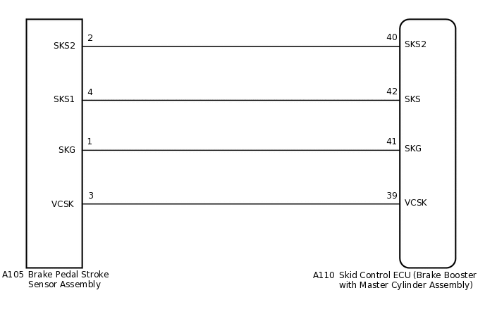
WIRING DIAGRAM
CAUTION / NOTICE / HINT
When replacing the skid control ECU (brake booster with master cylinder assembly) or brake pedal stroke sensor assembly, perform initialization and calibration of the linear solenoid valve.
PROCEDURE
CHECK BRAKE PEDAL
Check that the brake pedal and the brake pedal stroke sensor assembly are properly installed and that the pedal can be depressed normally.
Check and adjust the brake pedal height.
for LHD:Click here
for RHD:Click here
Adjust the brake pedal stroke sensor assembly.
Result
Proceed to
NEXT
CHECK HARNESS AND CONNECTOR (BRAKE BOOSTER WITH MASTER CYLINDER ASSEMBLY - BRAKE PEDAL STROKE SENSOR ASSEMBLY)
Make sure that there is no looseness at the locking part and the connecting part of the connectors.
Disconnect the A110 skid control ECU (brake booster with master cylinder assembly) connector.
Disconnect the A105 brake pedal stroke sensor assembly connector.
Check both the connector case and the terminal for deformation and corrosion.
OK
No deformation or corrosion.
Measure the resistance according to the value(s) in the table below.
Standard Resistance
Tester Connection
Condition
Specified Condition
A110-39 (VCSK) - A105-3 (VCSK)
Always
Below 1 Ω
A110-39 (VCSK) or A105-3 (VCSK) - Body ground
Always
10 kΩ or higher
A110-41 (SKG) - A105-1 (SKG)
Always
Below 1 Ω
A110-41 (SKG) or A105-1 (SKG) - Body ground
Always
10 kΩ or higher
A110-42 (SKS) - A105-4 (SKS1)
Always
Below 1 Ω
A110-42 (SKS) or A105-4 (SKS1) - Body ground
Always
10 kΩ or higher
A110-40 (SKS2) - A105-2 (SKS2)
Always
Below 1 Ω
A110-40 (SKS2) or A105-2 (SKS2) - Body ground
Always
10 kΩ or higher
Result
Proceed to
OK
NG
NG REPAIR OR REPLACE HARNESS OR CONNECTOR
INSPECT BRAKE BOOSTER WITH MASTER CYLINDER ASSEMBLY (SENSOR OUTPUT)
-
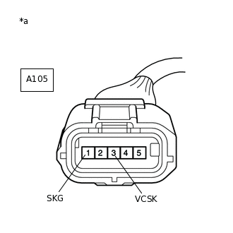
*a
Front view of wire harness connector
(to Brake Pedal Stroke Sensor Assembly)
Reconnect the A110 skid control ECU (brake booster with master cylinder assembly) connector.
Turn the power switch on (IG).
Measure the voltage according to the value(s) in the table below.
Standard Voltage
Tester Connection
Switch Condition
Specified Condition
A105-3 (VCSK) - A105-1 (SKG)
Power switch on (IG)
4.84 to 5.16 V
Result
Proceed to
OK
NG
-