FRONT PNEUMATIC CYLINDER(for 2WD) REMOVAL
CAUTION / NOTICE / HINT
The necessary procedures (adjustment, calibration, initialization, or registration) that must be performed after parts are removed, installed, or replaced during the front pneumatic cylinder removal/installation are shown below.
| Necessary Procedure After Parts Removed/Installed/Replaced | ||||||||||||||
|---|---|---|---|---|---|---|---|---|---|---|---|---|---|---|
|
Note
-
Be sure to read the "PRECAUTION" thoroughly before servicing.
-
In order to prevent the battery from becoming fully depleted, connect the battery charger to the battery when turning the engine switch on (IG) to charge the battery.
-
Keep the power supply connected to prevent the GTS battery from becoming fully depleted.
Tech Tips
-
Use the same procedure for the RH and LH side.
-
The following procedure is for the LH side.
PROCEDURE
-
AIR SUSPENSION CONTROL PROHIBITED (WHEN REPLACING A FRONT PNEUMATIC CYLINDER)
Tech Tips
Check each part and system if an error is displayed for air movement pattern A.
-
Connect the GTS to the DLC3 with the engine switch off.
-
Turn the engine switch on (IG).
-
Turn the GTS on and enter the following menus: Chassis / Air suspension / Utility / Air Transfer Pattern A.
Chassis > Air suspension > UtilityTester Display Air Transfer Pattern A -
Perform vehicle height control prohibition and air movement according to the instructions on the GTS.
-
-
AIR SUSPENSION CONTROL PROHIBITED (WHEN REPLACING THE 2 FRONT PNEUMATIC CYLINDERS)
Tech Tips
Check each part and system if an error is displayed for air movement pattern B.
-
Connect the GTS to the DLC3 with the engine switch off.
-
Turn the engine switch on (IG).
-
Turn the GTS on and enter the following menus: Chassis / Air suspension / Utility / Air Transfer Pattern B.
Chassis > Air suspension > UtilityTester Display Air Transfer Pattern B -
Perform vehicle height control prohibition and air movement according to the instructions on the GTS.
-
-
REMOVE UPPER RADIATOR SUPPORT SEAL (for LH Side)
-
REMOVE RADIATOR COVER PLATE (for RH Side)
-
REMOVE FRONT WHEEL
-
REMOVE ABSORBER CONTROL WIRE LH
-
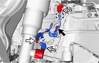

Bolt 
Nut 
Connector Remove the bolt and nut.
-
Disconnect the clamp, 2 connectors and remove the absorber control wire LH.
-
-
DISCONNECT FRONT STABILIZER LINK ASSEMBLY LH
-
DISCONNECT FRONT HEIGHT CONTROL SENSOR SUB-ASSEMBLY LH
-
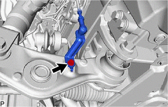
Remove the bolt and disconnect the front height control sensor sub-assembly LH.
-
-
DISCONNECT FRONT SKID CONTROL SENSOR WIRE LH
-
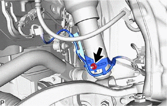
Remove the nut and disconnect the front skid control sensor wire LH.
-
-
DISCONNECT DISC BRAKE CYLINDER ASSEMBLY LH
-
DISCONNECT STEERING KNUCKLE ASSEMBLY LH
-
DISCONNECT NO.4 HEIGHT CONTROL TUBE
-
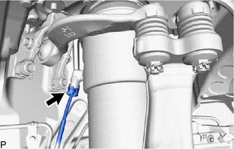
Disconnect the No. 4 height control tube from the front pneumatic cylinder with shock absorber assembly LH.
-
-
REMOVE FRONT SHOCK ABSORBER CAP LH
-
REMOVE FRONT PNEUMATIC CYLINDER WITH SHOCK ABSORBER ASSEMBLY LH
-
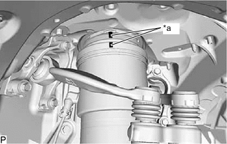
*a Matchmark When reusing the front pneumatic cylinder with shock absorber assembly LH:
-
Place matchmarks on the front suspension support assembly and pneumatic cylinder chamber.
-
-
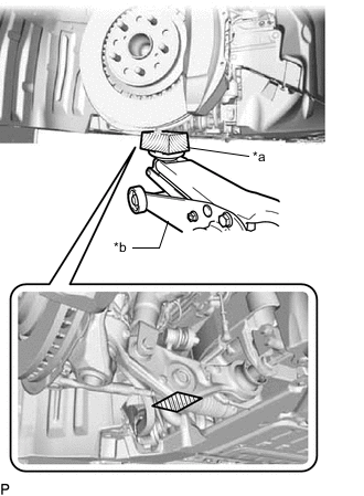
*a Wooden Block *b Jack Support the lower No. 2 suspension arm assembly LH using a jack and wooden block.
-
Remove the nut.
Note
-
Because the nut has its own stopper, do not turn the nut. Loosen the bolt with the nut secured.
-
Do not remove the bolt.
-
-
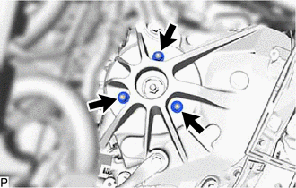
Remove the 3 nuts from the front pneumatic cylinder with shock absorber assembly LH (upper side).
-
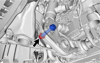
Remove the bolt from the front pneumatic cylinder with shock absorber assembly LH (lower side).
-
Slowly lower the jack and remove the front pneumatic cylinder with shock absorber assembly LH.
-
When reusing the front pneumatic cylinder with shock absorber assembly LH:
-
Remove the No. 2 connector, plate and 2 O-rings.
-
-