HEATED WINDSHIELD DEFROSTER SYSTEM Heated Windshield Defroster System does not operate
DESCRIPTION
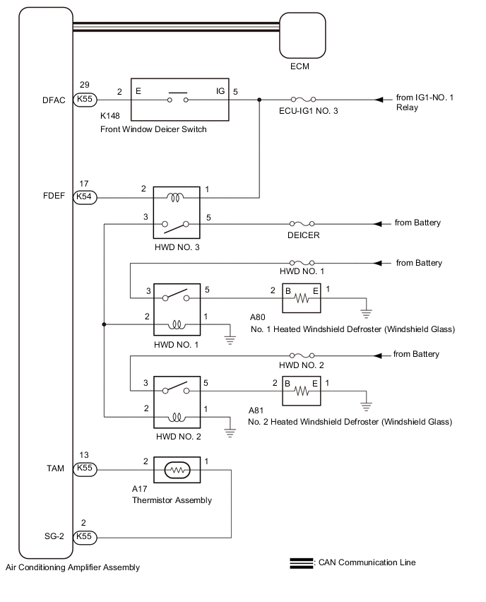
When the front window deicer switch assembly is operated, the operation signal is transmitted to the air conditioning amplifier assembly directly. When the air conditioning amplifier assembly receives the signal, it turns on the HWD NO. 1 relay, HWD NO. 2 relay and HWD NO. 3 relay to operate the heated windshield defroster system.
WIRING DIAGRAM
CAUTION / NOTICE / HINT
Note
-
Inspect the fuses for circuits related to this system before performing the following procedure.
-
If the battery voltage is low, the heated windshield defroster system may not operate due to operation of battery load control, check the Data List item "Battery Control Count (Body ECU)".
-
The heated windshield defroster system uses the CAN communication system. First, confirm that there are no malfunctions in the communication system by checking the communication function of the CAN communication system. Refer to the How to Proceed with Troubleshooting procedure
-
If the ambient temperature is 4.5°C (40°F) or higher, or if a malfunction of the ambient temperature sensor (thermistor assembly) is detected, the HWD NO. 3 relay will be deactivated and the front window deicer switch indicator light will blink.
PROCEDURE
-
CHECK FOR DTC
-
Clear the DTCs.
Body Electrical > Air Conditioner > Clear DTCs -
Recheck for DTCs.
Body Electrical > Air Conditioner > Trouble CodesResult Result Proceed to DTC B1412 is output A DTC B1412 is not output B
A 
GO TO AIR CONDITIONING SYSTEM (B1412) Click here
B 
-
-
PERFORM ACTIVE TEST USING GTS
-
Connect the GTS to the DLC3.
-
Turn the engine switch on (IG).
-
Turn the GTS on.
-
Enter the following menus: Body Electrical / Air Conditioner / Active Test.
-
Perform the Active Test according to the display on the GTS.
Body Electrical > Air Conditioner > Active TestTester Display Measurement Item Control Range Diagnostic Note HWD Relay Heated windshield defroster (windshield glass) OFF or ON -
Body Electrical > Air Conditioner > Active TestTester Display HWD Relay OK The heated windshield defroster system operates normally. Result Result Proceed to OK A NG (Both No. 1 and No. 2 heated windshield defroster does not warm up.) B NG (Only No. 1 heated windshield defroster does not warm up.) C NG (Only No. 2 heated windshield defroster does not warm up.) D
B 
INSPECT HWD NO. 3 RELAY Click here
C
INSPECT HWD NO. 1 RELAY Click here
D
INSPECT HWD NO. 2 RELAY Click here
A
-
-
INSPECT FRONT WINDOW DEICER SWITCH
-
Remove the front window deicer switch.
-
Inspect the front window deicer switch.
Result Proceed to OK NG
NG
REPLACE FRONT WINDOW DEICER SWITCH Click here
OK
-
-
CHECK WIRE HARNESS AND CONNECTOR (FRONT WINDOW DEICER SWITCH - IG POWER SUPPLY)
-
Disconnect the K148 front window deicer switch connector.
-
Measure the voltage according to the value(s) in the table below.
Standard Voltage Tester Connection Condition Specified Condition K148-5 (IG) - Body ground Engine switch off Below 1 V Engine switch on (IG) 11 to 14 V Result Proceed to OK NG
NG
REPAIR OR REPLACE HARNESS OR CONNECTOR
OK
-
-
CHECK WIRE HARNESS AND CONNECTOR (FRONT WINDOW DEICER SWITCH - AIR CONDITIONING AMPLIFIER ASSEMBLY)
-
Disconnect the K54 and K55 air conditioning amplifier assembly connectors.
-
Measure the resistance according to the value(s) in the table below.
Standard Resistance Tester Connection Condition Specified Condition K148-4 (D) - K54-22 (IND) Always Below 1 Ω K148-4 (D) or K54-22 (IND) - Body ground Always 10 kΩ or higher K148-2 (E) - K55-29 (DFAC) Always Below 1 Ω K148-2 (E) or K55-29 (DFAC) - Body ground Always 10 kΩ or higher Result Proceed to OK NG
OK
REPLACE AIR CONDITIONING AMPLIFIER ASSEMBLY Click here
NG
REPAIR OR REPLACE HARNESS OR CONNECTOR
-
-
INSPECT HWD NO. 3 RELAY
-
Inspect the HWD NO. 3 relay.
Result Proceed to OK NG
NG
REPLACE HWD NO. 3 RELAY
OK
-
-
CHECK WIRE HARNESS AND CONNECTOR (HWD NO. 3 RELAY - IG POWER SUPPLY)
-
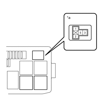
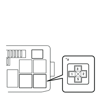
*a HWD No. 3 Relay Holder Measure the voltage according to the value(s) in the table below.
Standard Voltage Tester Connection Condition Specified Condition HWD NO. 3 relay holder terminal 1 - Body ground Engine switch on (IG) 11 to 14 V HWD NO. 3 relay holder terminal 5 - Body ground Always 11 to 14 V Result Proceed to OK NG
NG
REPAIR OR REPLACE HARNESS OR CONNECTOR
OK
-
-
CHECK WIRE HARNESS AND CONNECTOR (HWD NO. 3 RELAY - HWD NO. 1 RELAY OR HWD NO. 2 RELAY)
-
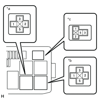
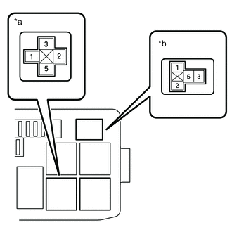
*a HWD No. 1 Relay Holder *b HWD No. 2 Relay Holder *c HWD No. 3 Relay Holder Disconnect K54 air conditioning amplifier assembly connector.
-
Measure the resistance according to the value(s) in the table below.
Standard Resistance Tester Connection Condition Specified Condition HWD NO. 3 relay holder terminal 3 - HWD NO. 1 relay holder terminal 2 or HWD NO. 2 relay holder terminal 2 Always Below 1 Ω HWD NO. 3 relay holder terminal 3 - Body ground Always 10 kΩ higher HWD NO. 1 relay holder terminal 2 - Body ground Always 10 kΩ higher HWD NO. 2 relay holder terminal 2 - Body ground Always 10 kΩ higher Result Proceed to OK NG
OK
REPLACE AIR CONDITIONING AMPLIFIER ASSEMBLY
NG
REPAIR OR REPLACE HARNESS OR CONNECTOR
-
-
INSPECT HWD NO. 1 RELAY
-
Inspect the HWD NO. 1 relay.
Result Proceed to OK NG
NG
REPLACE HWD NO. 1 RELAY
OK
-
-
CHECK WIRE HARNESS AND CONNECTOR (HWD NO. 1 RELAY - BATTERY)
-
*a HWD No. 1 Relay Holder Measure the voltage according to the value(s) in the table below.
Standard Voltage Tester Connection Condition Specified Condition HWD NO. 1 relay holder terminal 3 - Body ground Always 11 to 14 V Result Proceed to OK NG
NG
REPAIR OR REPLACE HARNESS OR CONNECTOR
OK
-
-
CHECK WIRE HARNESS AND CONNECTOR (HWD NO. 1 RELAY - HWD NO. 3 RELAY)
*a HWD No. 1 Relay Holder *b HWD No. 3 Relay Holder
-
Measure the resistance according to the value(s) in the table below.
Standard Resistance Tester Connection Condition Specified Condition HWD NO. 3 relay holder terminal 3 - HWD NO. 1 relay holder terminal 2 Always Below 1 Ω HWD NO. 3 relay holder terminal 3 or HWD NO. 1 relay holder terminal 2 - Body ground Always 10 kΩ higher Result Proceed to OK NG
NG
REPAIR OR REPLACE HARNESS OR CONNECTOR
OK
-
-
CHECK WIRE HARNESS AND CONNECTOR (HWD NO. 1 RELAY - BODY GROUND)
-
*a HWD No. 1 Relay Holder Measure the resistance according to the value(s) in the table below.
Standard Resistance Tester Connection Condition Specified Condition HWD NO. 1 relay holder terminal 1 - Body ground Always Below 1 Ω Result Proceed to OK NG
NG
REPAIR OR REPLACE HARNESS OR CONNECTOR
OK
-
-
CHECK WIRE HARNESS AND CONNECTOR (HWD NO. 1 RELAY - NO. 1 HEATED WINDSHIELD DEFROSTER (WINDSHIELD GLASS))
-
*a HWD No. 1 Relay Holder Disconnect A80 No. 1 heated windshield defroster (windshield glass) connector.
-
Measure the resistance according to the value(s) in the table below.
Standard Resistance Tester Connection Condition Specified Condition HWD NO. 1 relay holder terminal 5 - A80-2 (B) Always Below 1 Ω HWD NO. 1 relay holder terminal 5 or A80-2 (B) - Body ground Always 10 kΩ higher Result Proceed to OK NG
NG
REPLACE HARNESS OR CONNECTOR
OK
-
-
CHECK WIRE HARNESS AND CONNECTOR (NO. 1 HEATED WINDSHIELD DEFROSTER (WINDSHIELD GLASS) - BODY GROUND)
-
Measure the resistance according to the value(s) in the table below.
Standard Resistance Tester Connection Condition Specified Condition A80-1 (E) - Body ground Always Below 1 Ω Result Proceed to OK NG
OK
REPLACE WINDSHIELD GLASS
NG
REPAIR OR REPLACE HARNESS OR CONNECTOR
-
-
INSPECT HWD NO. 2 RELAY
-
Inspect the HWD NO. 2 relay.
Result Proceed to OK NG
NG
REPLACE HWD NO. 2 RELAY
OK
-
-
CHECK WIRE HARNESS AND CONNECTOR (HWD NO. 2 RELAY - BATTERY)
-
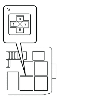
*a HWD No. 2 Relay Holder Measure the resistance according to the value(s) in the table below.
Standard Voltage Tester Connection Condition Specified Condition HWD NO. 2 relay holder terminal 3 - Body ground Always 11 to 14 V Result Proceed to OK NG
NG
REPAIR OR REPLACE HARNESS OR CONNECTOR
OK
-
-
CHECK WIRE HARNESS AND CONNECTOR (HWD NO. 2 RELAY - HWD NO. 3 RELAY)
-
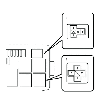
*a HWD No. 2 Relay Holder *b HWD No. 3 Relay Holder Measure the resistance according to the value(s) in the table below.
Standard Resistance Tester Connection Condition Specified Condition HWD NO. 3 relay holder terminal 3 - HWD NO. 2 relay holder terminal 2 Always Below 1 Ω HWD NO. 3 relay holder terminal 3 or HWD NO. 2 relay holder terminal 2 - Body ground Always 10 kΩ higher Result Proceed to OK NG
NG
REPAIR OR REPLACE HARNESS OR CONNECTOR
OK
-
-
CHECK WIRE HARNESS AND CONNECTOR (HWD NO. 2 RELAY - BODY GROUND)
-
*a HWD No. 2 Relay Holder Measure the resistance according to the value(s) in the table below.
Standard Resistance Tester Connection Condition Specified Condition HWD NO. 2 relay holder terminal 1 - Body ground Always Below 1 Ω Result Proceed to OK NG
NG
REPAIR OR REPLACE HARNESS OR CONNECTOR
OK
-
-
CHECK WIRE HARNESS AND CONNECTOR (HWD NO. 2 RELAY - NO. 2 HEATED WINDSHIELD DEFROSTER (WINDSHIELD GLASS))
-
*a HWD No. 2 Relay Holder Disconnect A81 No. 2 heated windshield defroster (windshield glass) connector.
-
Measure the resistance according to the value(s) in the table below.
Standard Resistance Tester Connection Condition Specified Condition HWD NO. 2 relay holder terminal 5 - A81-2 (B) Always Below 1 Ω HWD NO. 2 relay holder terminal 5 or A81-2 (B) - Body ground Always 10 kΩ higher Result Proceed to OK NG
NG
REPAIR OR REPLACE HARNESS OR CONNECTOR
OK
-
-
CHECK WIRE HARNESS AND CONNECTOR (NO. 2 HEATED WINDSHIELD DEFROSTER (WINDSHIELD GLASS) - BODY GROUND)
-
Measure the resistance according to the value(s) in the table below.
Standard Resistance Tester Connection Condition Specified Condition A81-1 (E) - Body ground Always Below 1 Ω Result Proceed to OK NG
OK
REPLACE WINDSHIELD GLASS
NG
REPAIR OR REPLACE HARNESS OR CONNECTOR
-