CYLINDER HEAD REASSEMBLY

CAUTION / NOTICE / HINT
Tech Tips
Perform "Inspection After Repairs" after replacing the cylinder head sub-assembly.
PROCEDURE
-
INSTALL SPARK PLUG TUBE
Tech Tips
When using a new cylinder head sub-assembly, the spark plug tubes must be replaced.
-
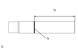
*a Protrusion Height *b Paint Mark Mark the standard protrusion height from the edge with paint.
Standard Protrusion Height 87.8 mm (3.46 in.) -
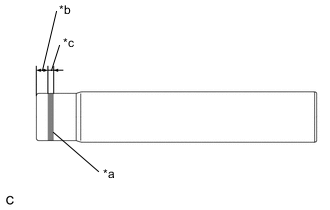
*a Adhesive 1324 *b 1.0 to 7.0 mm (0.0394 to 0.276 in.) *c 1.0 to 3.0 mm (0.0394 to 0.118 in.) Apply adhesive to the spark plug tube where it will be pressed into the cylinder head sub-assembly.
Adhesive Toyota Genuine Adhesive 1324, Three Bond 1324 or equivalent Note
Install the spark plug tube within 3 minutes of applying adhesive.
-
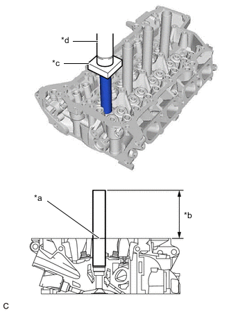
*a Paint Mark *b Protrusion Height *c Wooden Block *d Press Using a press and wooden block, install the 4 spark plug tubes to the specified protrusion height.
Standard Protrusion Height 87.8 mm (3.46 in.) Note
-
Do not tap in the spark plug tube more than specified.
-
Do not start the engine for at least 1 hour after installation.
-
Be careful not to deform the spark plug tubes.
-
Be careful not to spill any adhesive.
-
-
-
INSTALL NO. 1 STRAIGHT SCREW PLUG
Tech Tips
If coolant leaks from a No. 1 straight screw plug or a plug is corroded, replace it.
-
Apply adhesive to the 2 No. 1 straight screw plugs.
Adhesive Toyota Genuine Adhesive 1324, Three Bond 1324 or equivalent Note
Install the No. 1 straight screw plugs within 3 minutes of applying adhesive.
-
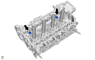
Using a 6 mm hexagon wrench, install the 2 No. 1 straight screw plugs to the cylinder head sub-assembly.
- Torque:
- 25 N*m { 255 kgf*cm, 18 ft.*lbf }
-
-
INSTALL NO. 2 STRAIGHT SCREW PLUG
Tech Tips
If coolant leaks from the No. 2 straight screw plug or the plug is corroded, replace it.
-
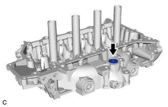
Using a 10 mm hexagon wrench, install a new cylinder head screw plug gasket and the No. 2 straight screw plug to the cylinder head sub-assembly.
- Torque:
- 44 N*m { 449 kgf*cm, 32 ft.*lbf }
-
-
INSTALL NO. 3 STRAIGHT SCREW PLUG
Tech Tips
If coolant leaks from a No. 3 straight screw plug or a plug is corroded, replace it.
-
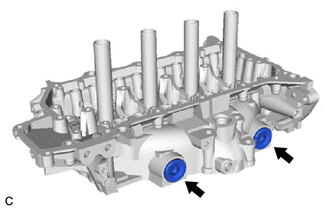
Using a 14 mm hexagon wrench, install 2 new No. 2 cylinder head screw plug gaskets and the 2 No. 2 straight screw plugs to the cylinder head sub-assembly.
- Torque:
- 80 N*m { 816 kgf*cm, 59 ft.*lbf }
-
-
INSTALL VALVE SPRING SEAT
-
Install the 16 valve spring seats to the cylinder head sub-assembly.
-
-
INSTALL INTAKE VALVE STEM OIL SEAL
-
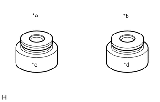
*a Intake Side *b Exhaust Side *c Gold *d Gray Apply a light coat of engine oil to new valve stem oil seals.
Note
Pay attention when installing the intake valve stem oil seals. For example, installing an intake side valve stem oil seal to the exhaust side or installing an exhaust side valve stem oil seal to the intake side can cause installation problems later.
Tech Tips
The intake side valve stem oil seal is gold and the exhaust side valve stem oil seal is gray.
-
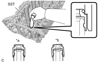
*a Correct *b Incorrect Using SST, push in the 16 valve stem oil seals.
- SST
- 09201-41020
Note
-
Failure to use SST will cause the intake valve stem oil seal to be damaged or improperly seated.
-
Do not push in the intake valve stem oil seals at an angle.
-
-
INSTALL EXHAUST VALVE STEM OIL SEAL
Tech Tips
Use the same procedure as for the intake side.
-
INSTALL EXHAUST VALVE
-
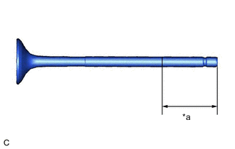
*a 30 mm (1.18 in.) or more Sufficiently apply engine oil to the tip area of the exhaust valve shown in the illustration.
-
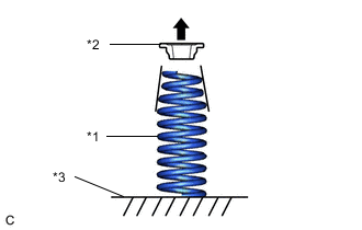
*1 Inner Compression Spring *2 Valve Spring Retainer *3 Cylinder Head Sub-assembly 
Top Side Install the 8 exhaust valves, 8 inner compression springs and 8 valve spring retainers to the cylinder head sub-assembly.
Note
-
Install the inner compression spring with its tapered side facing upward (towards the valve spring retainer).
-
Install the same parts in the same combination to their original locations.
-
-
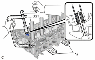
*a Wooden Block Using SST and wooden blocks, compress the inner compression spring and install the 8 valve spring retainer locks.
- SST
- 09202-70020
- 09202-00020
Note
Install the same parts in the same combination to their original locations.
-
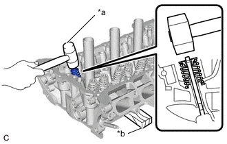
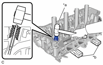
*a Plastic Hammer *b Wooden Block Using a plastic hammer, lightly tap the valve stem tip to ensure a proper fit.
Note
-
Be careful not to damage the valve stem tip.
-
Be careful not to damage the valve spring retainer.
-
-
-
INSTALL INTAKE VALVE
-
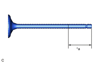
*a 30 mm (1.18 in.) or more Sufficiently apply engine oil to the tip area of the intake valve shown in the illustration.
-
*1 Inner Compression Spring *2 Valve Spring Retainer *3 Cylinder Head Sub-assembly Top Side Install the 8 intake valves, 8 inner compression springs and 8 valve spring retainers to the cylinder head sub-assembly.
Note
-
Install the inner compression spring with its tapered side facing upward (towards the valve spring retainer).
-
Install the same parts in the same combination to their original locations.
-
-
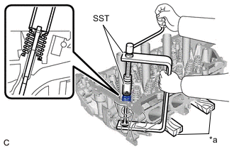
*a Wooden Block Using SST and wooden blocks, compress the inner compression spring and install the 8 valve spring retainer locks.
- SST
- 09202-70020
- 09202-00020
Note
Install the same parts in the same combination to their original locations.
-
*a Plastic Hammer *b Wooden Block Using a plastic hammer, lightly tap the valve stem tip to ensure a proper fit.
Note
-
Be careful not to damage the valve stem tip.
-
Be careful not to damage the valve spring retainer.
-
-