LEXUS PARKING ASSIST-SENSOR SYSTEM
-
FUNCTION OF MAIN COMPONENTS
Component Function Clearance Warning ECU Assembly
-
Judges the approximate distance between the vehicle and an obstacle based on signals from the ultrasonic sensors. Output signals are sent to the combination meter assembly or radio receiver assembly.
-
Sounds each clearance warning buzzer.
No. 1 Ultrasonic Sensor Detects the distance between the vehicle and an obstacle. No. 1 Clearance Warning Buzzer Sounds to inform the driver according to the distance to the obstacle in front of the vehicle. No. 2 Clearance Warning Buzzer Sounds to inform the driver according to the distance to the obstacle behind the vehicle. Combination Meter Assembly Lexus Parking Assist-sensor System Indicator Light Illuminates to inform the driver when the system operation conditions are met. Multi-information Display
-
Displays the location of the obstacle and the approximate distance between the vehicle and the obstacle.
-
Sends Lexus parking assist-sensor system on/off signals to the clearance warning ECU assembly.
-
The sound volume, distance required to sound the buzzer and distance required to trigger the display can be chosen on the setup screen for the Lexus parking assist-sensor system.
-
Displays the mute function setting screen.
-
Displays an indication of a malfunction or freezing of an ultrasonic sensor to inform the driver.
Master Warning Light Illuminates when the Lexus parking assist-sensor system is malfunctioning. Meter Buzzer Sounds when the Lexus parking assist-sensor system is malfunctioning. Multi-display Assembly Displays the location of an obstacle and the approximate distance between the vehicle and the obstacle. Steering Pad Switch Assembly Sends operation signals from switches to the combination meter assembly. Park/Neutral Position Switch Assembly Transmits the shift position signal to the ECM. Remote Touch (Remote Operation Controller Assembly) Transmits operation signals to the radio receiver assembly. Parking Assist ECU*1 The clearance sonar information is superimposed on the captured image. Then, the image is sent to the multi-display assembly as video signals. Rear Television Camera Assembly*2
-
Captures images of the area behind the vehicle.
-
The clearance sonar information is superimposed on the captured image. Then, the image is sent to the multi-display assembly as video signals.
Skid Control ECU Sends the vehicle speed signal to the clearance warning ECU assembly. Air Conditioning Amplifier Assembly Sends outside temperature information to the clearance warning ECU assembly. Radio Receiver Assembly
-
Displays a video from the parking assist ECU on the multi-display assembly.*1
-
Displays a video from the rear television camera assembly on the multi-display assembly.*2
ECM Sends the shift position signal to the clearance warning ECU assembly. Central Gateway ECU (Network Gateway ECU) Relays the signal between the CAN communication lines. *1: Models with panoramic view monitor system
*2: Models with parking assist monitor system
-
-
OPERATING CONDITION
-
The operating condition of each sensor differs according to its installed position as shown in the table below:
Installation Position Operating Condition Front Corner
-
Engine switch is on (IG).
-
System is activated.
-
Shift lever is not in P.
-
Vehicle speed is approximately 10 km/h (6 mph) or less.
Front Center
-
Engine switch is on (IG).
-
System is activated.
-
Shift lever is not in P and R.
-
Vehicle speed is approximately 10 km/h (6 mph) or less.
Rear Center
-
Engine switch is on (IG).
-
System is activated.
-
Shift lever is in R.
-
Vehicle speed is approximately 10 km/h (6 mph) or less.
Rear Corner -
-
-
SYSTEM CONTROL
-
Detection Area
-
The detection areas of the ultrasonic sensor are as shown in the following illustration.
-
These detection areas are applicable when positioning a 60 mm (2.36 in.) diameter pole parallel or perpendicular to the ground. The ranges vary depending on the measuring method and type of obstacle.
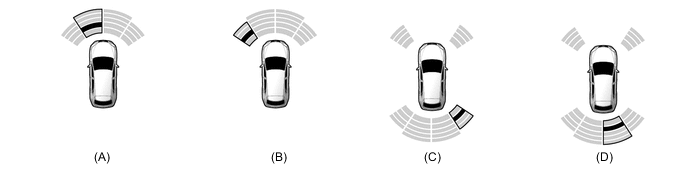
Figure 1. Corner Area
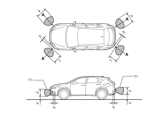
*a Approximately 850 mm (33.5 in.) *b Approximately 200 mm (7.87 in.) *c Approximately 600 mm (23.6 in.) *d Approximately 450 mm (17.7 in.) *e Approximately 350 mm (13.8 in.) - - 
Detection Area - - Note
The ultrasonic sensor side view detection range area (labeled (1)) represents the cross section of the top view of the lines of detection range A. The area (1) does not represent the entire side view detection range.
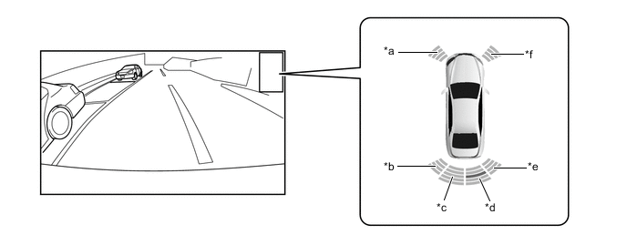
Figure 2. Center Area
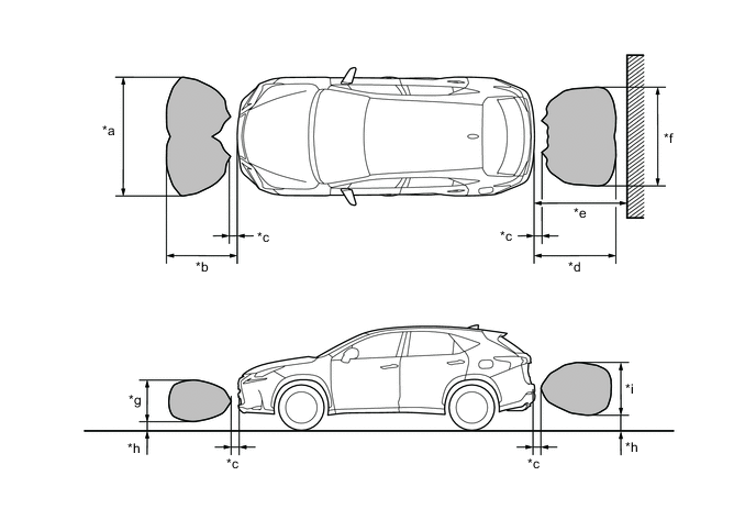
*a Approximately 2000 mm (78.7 in.) *b Approximately 1000 mm (39.4 in.) *c Approximately 200 mm (7.87 in.) *d Approximately 1250 mm (49.2 in.) *e Approximately 1500 mm (59.1 in.) *f Approximately 1900 mm (74.8 in.) *g Approximately 500 mm (19.7 in.) *h Approximately 300 mm (11.8 in.) *i Approximately 600 mm (23.6 in.) - - Detection Area - -
-
-
Detective Information Indication
-
The location of an obstacle and the approximate distance between the vehicle and the obstacle are displayed on the multi-information display in the combination meter assembly and multi-display assembly.
-
Indication on Multi-information Display
-
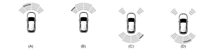
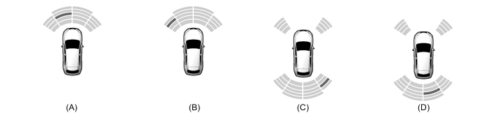
When the front center sensor or rear center sensor detects an obstacle, the location and approximate distance are indicated using 5 patterns: "Longest", "Long", "Middle", "Short" and "Shortest".
-
When the front corner sensor or rear corner sensor detects an obstacle, the location and approximate distance are indicated using 4 patterns: "Long", "Middle", "Short" and "Shortest".
Figure 3. Longest (Yellow Illuminates)

Sensor Position Detection Distance (A) Front Center 650 mm +/- 60 mm to 1000 mm +/- 110 mm (25.6 in. +/- 2.36 in. to 39.4 in. +/- 4.33 in.) (B) Rear Center 650 mm +/- 60 mm to 1500 mm +/- 110 mm (25.6 in. +/- 2.36 in. to 59.1 in. +/- 4.33 in.) Figure 4. Long (Yellow Illuminates)
Sensor Position Detection Distance (A) Front Center 450 mm +/- 50 mm to 650 mm +/- 60 mm (17.7 in. +/- 1.97 in. to 25.6 in. +/- 2.36 in.) (B) Front Corner 450 mm +/- 50 mm to 650 mm +/- 60 mm (17.7 in. +/- 1.97 in. to 25.6 in. +/- 2.36 in.) (C) Rear Corner 450 mm +/- 50 mm to 650 mm +/- 60 mm (17.7 in. +/- 1.97 in. to 25.6 in. +/- 2.36 in.) (D) Rear Center 450 mm +/- 50 mm to 650 mm +/- 60 mm (17.7 in. +/- 1.97 in. to 25.6 in. +/- 2.36 in.) Figure 5. Middle (Yellow Illuminates)
Sensor Position Detection Distance (A) Front Center 300 mm +/- 40 mm to 450 mm +/- 50 mm (11.8 in. +/- 1.57 in. to 17.7 in. +/- 1.97 in.) (B) Front Corner 300 mm +/- 40 mm to 450 mm +/- 50 mm (11.8 in. +/- 1.57 in. to 17.7 in. +/- 1.97 in.) (C) Rear Corner 300 mm +/- 40 mm to 450 mm +/- 50 mm (11.8 in. +/- 1.57 in. to 17.7 in. +/- 1.97 in.) (D) Rear Center 300 mm +/- 40 mm to 450 mm +/- 50 mm (11.8 in. +/- 1.57 in. to 17.7 in. +/- 1.97 in.) Figure 6. Short (Red Illuminates and Blinks)
Sensor Position Detection Distance (A) Front Center 150 mm +/- 40 mm to 300 mm +/- 40 mm (5.91 in. +/- 1.57 in. to 11.8 in. +/- 1.57 in.) (B) Front Corner 150 mm +/- 40 mm to 300 mm +/- 40 mm (5.91 in. +/- 1.57 in. to 11.8 in. +/- 1.57 in.) (C) Rear Corner 150 mm +/- 40 mm to 300 mm +/- 40 mm (5.91 in. +/- 1.57 in. to 11.8 in. +/- 1.57 in.) (D) Rear Center 150 mm +/- 40 mm to 300 mm +/- 40 mm (5.91 in. +/- 1.57 in. to 11.8 in. +/- 1.57 in.) Figure 7. Shortest (Red Illuminates and Blinks)

Sensor Position Detection Distance (A) Front Center 150 mm +/- 40 mm or less (5.91 in. +/- 1.57 in. or less) (B) Front Corner 150 mm +/- 40 mm or less (5.91 in. +/- 1.57 in. or less) (C) Rear Corner 150 mm +/- 40 mm or less (5.91 in. +/- 1.57 in. or less) (D) Rear Center 150 mm +/- 40 mm or less (5.91 in. +/- 1.57 in. or less)
-
-
Indication on Multi-display Assembly (Models with Parking Assist Monitor System)
-
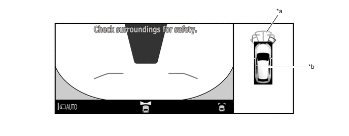
If an obstacle is detected when the parking assist monitor system is activated, the approximate distance between the vehicle and the obstacle is displayed on the multi-display assembly.
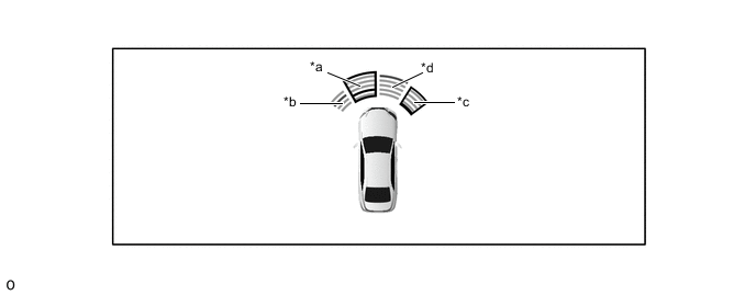
*a Front Corner LH *b Rear Corner LH *c Rear Center LH *d Rear Center RH *e Rear Corner RH *f Front Corner RH -
When an obstacle is detected while the vehicle is moving forward, the approximate distance between the vehicle and the obstacle is displayed on the multi-display assembly.
*a Front Center LH *b Front Corner LH *c Front Corner RH *d Front Center RH -
When the front center sensor or rear center sensor detects an obstacle, the location and approximate distance are indicated using 5 patterns: "Longest", "Long", "Middle", "Short" and "Shortest".
-
When the front corner sensor or rear corner sensor detects an obstacle, the location and approximate distance are indicated using 4 patterns: "Long", "Middle", "Short" and "Shortest".
-
-
Indication on Multi-display Assembly (Models with Panoramic View Monitor System)
-
If an obstacle is detected when the panoramic view monitor system is activated, the approximate distance between the vehicle and the obstacle is displayed on the multi-display assembly.
*a Obstacle Detection Information *b Panoramic View Vehicle Icon 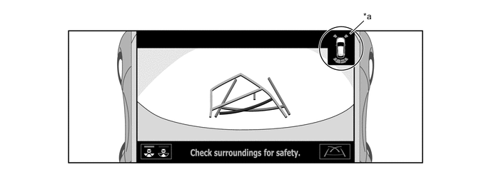
*a Obstacle Detection Information - - -
When the front center sensor or rear center sensor detects an obstacle, the location and approximate distance are indicated using 5 patterns: "Longest", "Long", "Middle", "Short" and "Shortest".
-
When the front corner sensor or rear corner sensor detects an obstacle, the location and approximate distance are indicated using 4 patterns: "Long", "Middle", "Short" and "Shortest".
-
-
-
Warning Buzzer Sounding
-
The warning buzzer sound changes according to the distance from an identified obstacle.
-
The buzzer sounding interval changes approximately every 100 mm (3.94 in.) according to the distance from the obstacle.
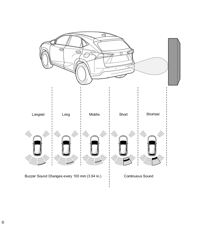
Identification Level Buzzer Sound Longest The sound interval changes every 100 mm (3.94 in.), and then sounds intermittently. Long Middle Short Sounds consecutively. Shortest -
If sensors detect multiple obstacles, the buzzer sounds according to the distance from the closest obstacle.
-
-
-
FUNCTION
-
System Setting
-
Each clearance warning buzzer audio volume can be adjusted and the Lexus parking assist-sensor system can be turned on and off by operating the multi-information display using the steering pad switch assembly.
-
-
Warning Buzzer Mute Function
-
When the warning buzzer is sounding, it is automatically muted if any of the following conditions are established.
-
There is no change to the distance from the obstacle over a certain period of time.
-
The distance between the vehicle and obstacle increases.
-
The obstacle is removed from the path.
-
-
When the warning buzzer has been automatically muted, it once again begins sounding if any of the following conditions are established.
-
An obstacle is detected within short-range.
-
The vehicle approaches an obstacle.
-
An obstacle that was out of the path of the vehicle is now on the path of the vehicle.
-
-
When the warning buzzer is sounding, the warning buzzer is temporarily muted if the steering pad switch assembly is used to do so.
-
When the warning buzzer has been temporarily muted, temporary muting is canceled if any of the following conditions are established.
-
The shift status is changed.
-
The vehicle speed reaches a certain value or higher.
-
There is a sensor abnormality (open/frozen).
-
It cannot be used (CAN communication abnormality).
-
The main switch of the Lexus parking assist-sensor system was turned off.
-
The engine switch was turned off.
-
-
-
Sensor Check Function
-
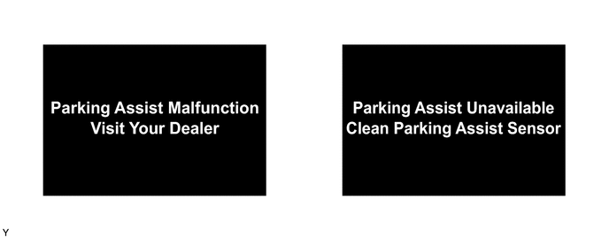
After the system power source is turned on, all sensors are checked regardless of the vehicle speed and shift position. If there is an open circuit or freezing malfunction in the sensor, the multi-information display in the combination meter assembly displays a warning message and the meter buzzer sounds to inform the driver. In addition, each sensor is checked for malfunctions even when obstacles are being detected. If a malfunction occurs, a warning message is also displayed.
-
-
-
DIAGNOSIS
-
If a system malfunction is detected, the clearance warning ECU assembly stores Diagnostic Trouble Codes (DTCs) in its memory. For details, refer to the Repair Manual.
-