WIRELESS DOOR LOCK CONTROL SYSTEM (for Built-in Type Door Control Receiver) No Answer-back
DESCRIPTION
In some cases, wireless control functions are normal but one or more of the following may occur:
-
The hazard warning light answer-back function is not normal (the theft warning ECU assembly's turn signal flasher assembly output may be malfunctioning).
-
The security horn answer-back function is not normal (the security horn assembly signal output may be malfunctioning)*.
Tech Tips
*: The security horn applies only if the wireless answer-back function has been customized so that the hazard warning lights flash and the security horn sounds.
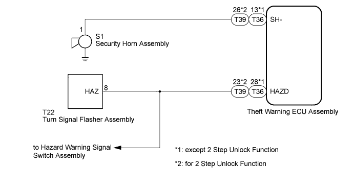
WIRING DIAGRAM
INSPECTION PROCEDURE
Note
When replacing the theft warning ECU assembly, refer to the registration procedures Click here.
PROCEDURE
-
CHECK WIRELESS DOOR LOCK CONTROL FUNCTION
-
Check the wireless door lock functions by operating the transmitter switches.
Result Result Proceed to Only hazard warning light and side turn signal light answer-back does not occur A Only security horn answer-back does not occur B Tech Tips
The security horn applies only if the wireless answer-back function has been customized so the hazard warning lights flash and the security horn sounds.
B 
Go to THEFT DETERRENT SYSTEM Click here
A 
-
-
CHECK HAZARD WARNING LIGHTS
-
Check that the hazard warning lights flash when the hazard warning signal switch is pressed.
OK Hazard warning lights flash.
NG
Go to LIGHTING SYSTEM Click here
OK
-
-
CHECK HARNESS AND CONNECTOR (THEFT WARNING ECU - TURN SIGNAL FLASHER)
-
Disconnect the T36*1 or T39*2 theft warning ECU assembly connector.
-
*1: except 2 Step Unlock Function
-
*2: for 2 Step Unlock Function
-
-
Disconnect the T22 turn signal flasher assembly connector.
-
Measure the resistance according to the value(s) in the table below.
Standard Resistance except 2 Step Unlock Function Tester Connection Condition Specified Condition T36-28 (HAZD) - T22-8 (HAZ) Always Below 1 Ω T36-28 (HAZD) or T22-8 (HAZ) - Body ground Always 10 kΩ or higher for 2 Step Unlock Function Tester Connection Condition Specified Condition T39-23 (HAZD) - T22-8 (HAZ) Always Below 1 Ω T39-23 (HAZD) or T22-8 (HAZ) - Body ground Always 10 kΩ or higher
NG
REPAIR OR REPLACE HARNESS OR CONNECTOR
OK 
REPLACE THEFT WARNING ECU ASSEMBLY
-