STARTER(w/o Stop And Start System) REASSEMBLY
PROCEDURE
INSTALL STARTER CLUTCH SUB-ASSEMBLY
-
*a
Pin without Depression

High-temperature Grease
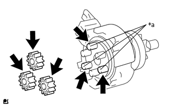
Apply high-temperature grease to the 3 planet gears and starter clutch sub-assembly.
Tip:Apply approximately 0.5 g of high-temperature grease to the planet gear section, end section and pins without depressions.
-
*a
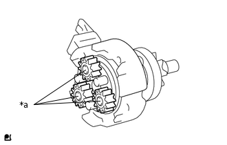
Pin without Depression
Install the 3 planetary gears to the pins without depressions on the starter clutch sub-assembly.
-
Engage the 3 claws and install the shock absorber to the starter clutch sub-assembly.
-
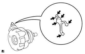
High-temperature Grease
Apply high-temperature grease to the drive lever contact surface.
Tip:Apply approximately 0.1 g of high-temperature grease to each section.
-
*a
Depression
*b
Protrusion
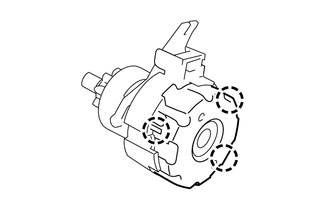
Align the depression of the starter drive housing with the protrusion of the starter clutch sub-assembly and install the starter clutch sub-assembly.
-
Install the rubber seal to the starter drive housing.
-
INSTALL STARTER BRUSH HOLDER ASSEMBLY
-
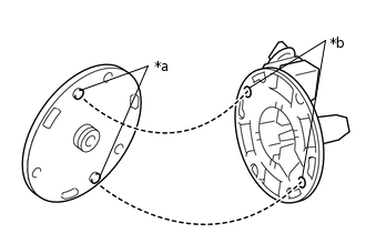
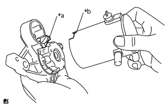
*a
Protrusion
*b
Depression
Install the commutator end frame to the starter brush holder assembly as shown in the illustration.
Tip:If the bolt holes are misaligned, the through bolts cannot be installed.
-
Spread the brushes on the starter brush holder assembly, and install the starter armature assembly to the starter brush holder assembly.
-
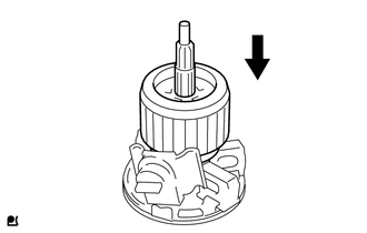
INSTALL STARTER ARMATURE ASSEMBLY
-
*a
Hammer
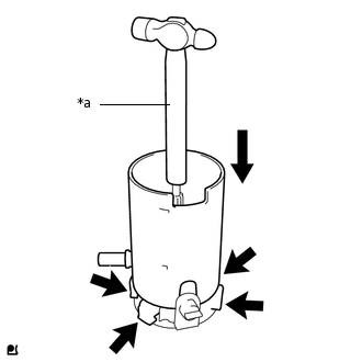
While holding down the starter armature assembly and the starter brush holder assembly with the handle of a hammer, install the starter yoke assembly.
Tip:The starter armature assembly will be attracted by the magnetic field of the starter yoke assembly, so hold the starter armature assembly with the handle of the hammer.
-
INSTALL STARTER YOKE ASSEMBLY
-
*a
Protrusion
*b
Cutout
Align the cutout of the starter yoke assembly with the protrusion of the starter clutch sub-assembly.
-
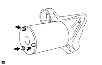
Using a 7 mm socket driver, install the starter yoke assembly with the 3 through bolts.
3.0 N*m
31 kgf*cm
27 in.*lbf
-
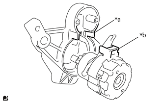
INSTALL MAGNET STARTER SWITCH ASSEMBLY
-
*a
Drive Lever
*b
Hook
Catch the hook on the magnet starter switch assembly on the drive lever from the top of the lever.
-
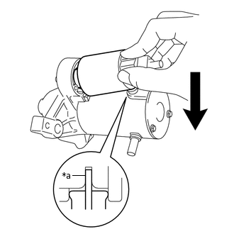
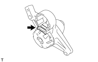
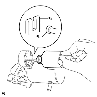
*a
Terminal C
While pushing down the rear of the magnet starter switch assembly, connect it to terminal C.
Note:Connect the magnet starter switch assembly securely to terminal C.
Check that the parts are free of foreign matter, oil, or grease.
-
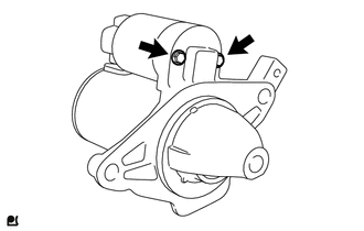
using a 7 mm socket driver, install the magnet starter switch assembly with the 2 bolts.
3.0 N*m
31 kgf*cm
27 in.*lbf
-