MONOLITHIC CONVERTER INSTALLATION
CAUTION / NOTICE / HINT
Perform "Inspection After Repair" after replacing the exhaust manifold converter sub-assembly (Click here).
PROCEDURE
INSTALL EXHAUST MANIFOLD CONVERTER SUB-ASSEMBLY
Tip:Perform "Inspection After Repair" after replacing the exhaust manifold converter sub-assembly (Click here).
-
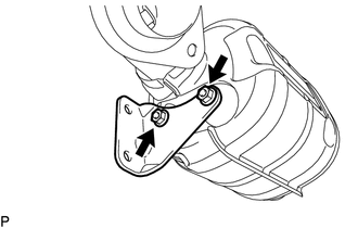
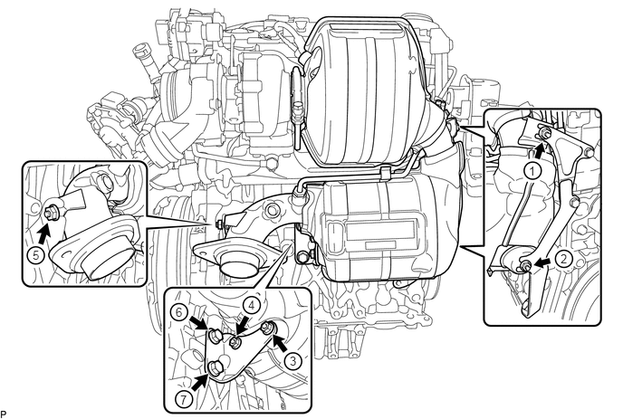
Temporarily install the manifold stay with the 2 nuts.
-
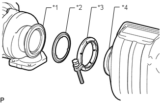
Temporarily install the exhaust manifold converter sub-assembly and engine bracket with the 3 nuts, 3 bolts, new V-band clamp and new gasket.
Table 1. Text in Illustration *1
Turbocharger Sub-assembly
*2
Gasket
*3
V-band Clamp
*4
Exhaust Manifold Converter Sub-assembly
Tighten the engine bracket with the 3 bolts.
19 N*m
194 kgf*cm
14 ft.*lbf
-
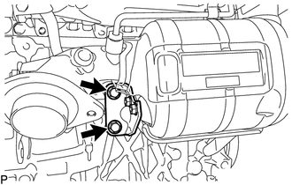
Temporarily install the manifold stay with the 2 bolts.
-
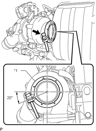
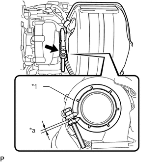
Align the V-band clamp as shown in the illustration and temporarily install it.
3.0 N*m
31 kgf*cm
27 in.*lbf
Table 2. Text in Illustration *1
V-band Clamp
Tip:To prevent the V-band clamp from interfering with the No. 1 manifold converter insulator, temporarily install the V-band clamp at the angle shown in the illustration.
-
Tighten the V-band clamp.
15 N*m
153 kgf*cm
11 ft.*lbf
Table 3. Text in Illustration *1
V-band Clamp
*a
Clearance
Check the clearance of the V-band clamp.
Note:Do not reuse a V-band clamp that has been tightened to the specified torque.
Tip:After tightening the V-band clamp to the specified torque, check that the clearance is within 0 to 3.5 mm (0 to 0.138 in.). If the result is not as specified, reinstall the exhaust manifold converter sub-assembly as the installation position is incorrect.
Tighten the 5 nuts, 2 bolts and exhaust manifold converter sub-assembly in the order shown in the illustration.
for bolt
38 N*m
387 kgf*cm
28 ft.*lbf
for nut
19 N*m
194 kgf*cm
14 ft.*lbf
-
INSTALL NO. 1 EXHAUST MANIFOLD HEAT INSULATOR
Install the No. 1 exhaust manifold heat insulator with the 2 bolts.
8.0 N*m
82 kgf*cm
71 in.*lbf
Attach the 2 clamps and connect the engine wire.
INSTALL FRONT EXHAUST PIPE ASSEMBLY
Check the free length of the compression spring.
-
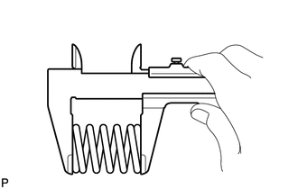
Using a vernier caliper, measure the free length of the compression spring.
Minimum length
41.5 mm (1.63 in.)
If the free length is less than the minimum, replace the compression spring.
-
-
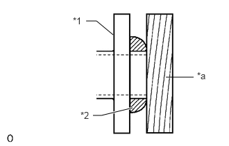
Using a plastic-faced hammer and wooden block, tap in a new gasket until its surface is flush with the exhaust manifold converter sub-assembly.
Table 4. Text in Illustration *1
Exhaust Manifold Converter Sub-assembly
*2
Gasket
*a
Wooden Block
Note:Be sure to install the gasket so that it faces the correct direction.
Do not reuse the gasket.
Do not damage the gasket.
When connecting the exhaust pipe, do not push in the gasket with the exhaust pipe.
Install a new gasket to the front exhaust pipe assembly.
Connect the front exhaust pipe assembly to the 3 exhaust pipe supports.
Install the front exhaust pipe assembly with the 4 bolts and 4 compression springs.
43 N*m
438 kgf*cm
32 ft.*lbf
INSTALL FRONT FLOOR CENTER BRACE
INSTALL NO. 2 ENGINE UNDER COVER
INSTALL OUTER COWL TOP PANEL
INSTALL WINDSHIELD WIPER MOTOR ASSEMBLY
INSTALL HEATER WITH EXHAUST PIPE ASSEMBLY (w/ Combustion Type Power Heater)
INSTALL DIFFERENTIAL PRESSURE SENSOR
INSTALL EXHAUST GAS TEMPERATURE SENSOR
for Sensor 1: (Click here)
for Sensor 2: (Click here)
INSTALL AIR FUEL RATIO SENSOR
for Sensor 1: (Click here)
for Sensor 2: (Click here)
INSPECT FOR EXHAUST GAS LEAK
PERFORM INITIALIZATION
Perform DPF history information reset (Click here).
Perform NOx storage catalyst learning value reset (Click here).