STEERING PAD SWITCH INSPECTION
PROCEDURE
INSPECT STEERING PAD SWITCH ASSEMBLY (for TMMT Made with Back Switch of Steering Pad Switch Assembly)
Measure the resistance according to the value(s) in the table below.
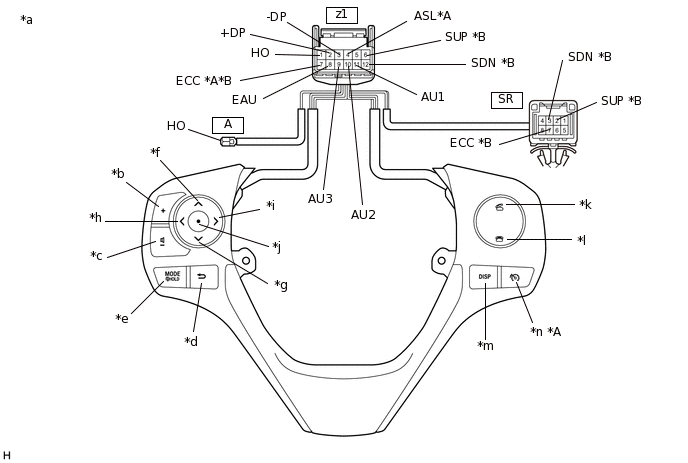
*A
w/ Speed Limiter System
*B
w/ Shift Paddle Switch
*a
Component without harness connected
(Steering Pad Switch Assembly)
*b
Volume+
*c
Volume-
*d
Back
*e
MODE/HOLD
*f
Seek+
*g
Seek-
*h
Left
*i
Right
*j
Enter
*k
Off hook
*l
On hook
*m
DISP
*n
Speed limiter
Standard Resistance
Tester Connection
Condition
Specified Condition
z1-1 (HO) - A-1 (HO)
Always
Below 2.5 Ω
z1-11 (AU1) - z1-8 (EAU)
No switch pushed
95 to 105 kΩ
Seek+ switch pushed
Below 2.5 Ω
Seek- switch pushed
313 to 345 Ω
Volume+ switch pushed
950 to 1050 Ω
Volume- switch pushed
2955 to 3265 Ω
z1-10 (AU2) - z1-8 (EAU)
No switch pushed
95 to 105 kΩ
MODE/HOLD switch pushed
Below 2.5 Ω
On hook switch pushed
313 to 345 Ω
Off hook switch pushed
950 to 1050 Ω
z1-9 (AU3) - z1-8 (EAU)
No switch pushed
95 to 105 kΩ
Enter switch pushed
Below 2.5 Ω
Back switch pushed
313 to 345 Ω
Right switch pushed
950 to 1050 Ω
Left switch pushed
2955 to 3265 Ω
z1-2 (+DP) - z1-3 (-DP)
No switch pushed
1 MΩ or higher
DISP switch pushed
Below 2.5 Ω
z1-4 (ASL) - z1-7 (ECC)*1
No switch pushed
1 MΩ or higher
Speed limiter switch pushed
Below 2.5 Ω
z1-6 (SUP) - SR-2 (SUP)*2
Always
Below 2.5 Ω
z1-7 (ECC) - SR-7 (ECC)*2
Always
Below 2.5 Ω
z1-12 (SDN) - SR-3 (SDN)*2
Always
Below 2.5 Ω
*1: w/ Speed Limiter System
*2: w/ Shift Paddle Switch
Tip:If the result is not as specified, replace the steering pad switch assembly.
Check the illumination.
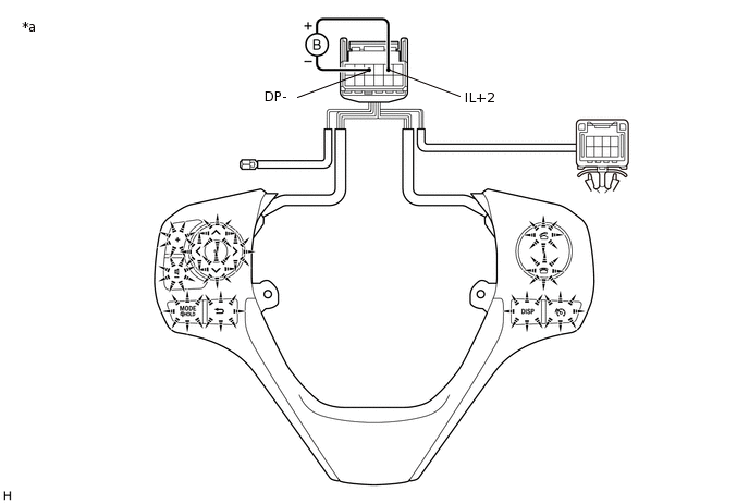
*a
Component without harness connected
(Steering Pad Switch Assembly)
-
-
Connect a positive (+) lead from the battery to terminal 5 (IL+2) and a negative (-) lead to terminal 3 (-DP) of the steering pad switch assembly connector.
Check that the steering pad switch assembly illumination illuminates.
OK
The steering pad switch assembly illumination illuminates.
Tip:If the result is not as specified, replace the steering pad switch assembly.
INSPECT STEERING PAD SWITCH ASSEMBLY (for TMMT Made without Back Switch of Steering Pad Switch Assembly)
Measure the resistance according to the value(s) in the table below.
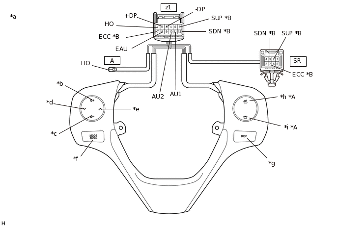
*A
w/ Microphone
*B
w/ Shift Paddle Switch
*a
Component without harness connected
(Steering Pad Switch Assembly)
*b
Volume+
*c
Volume-
*d
Seek-
*e
Seek+
*f
MODE/HOLD
*g
DISP
*h
Off hook
*i
On hook
-
-
Standard Resistance
Tester Connection
Condition
Specified Condition
z1-1 (HO) - A-1 (HO)
Always
Below 2.5 Ω
z1-11 (AU1) - z1-8 (EAU)
No switch pushed
95 to 105 kΩ
Seek+ switch pushed
Below 2.5 Ω
Seek- switch pushed
313 to 345 Ω
Volume+ switch pushed
950 to 1050 Ω
Volume- switch pushed
2955 to 3265 Ω
z1-10 (AU2) - z1-8 (EAU)
No switch pushed
95 to 105 kΩ
MODE/HOLD switch pushed
Below 2.5 Ω
On hook switch pushed*1
313 to 345 Ω
Off hook switch pushed*1
950 to 1050 Ω
z1-2 (+DP) - z1-3 (-DP)
No switch pushed
1 MΩ or higher
DISP switch pushed
Below 2.5 Ω
z1-6 (SUP) - SR-2 (SUP)*2
Always
Below 2.5 Ω
z1-7 (ECC) - SR-7 (ECC)*2
Always
Below 2.5 Ω
z1-12 (SDN) - SR-3 (SDN)*2
Always
Below 2.5 Ω
*1: w/ Microphone
*2: w/ Shift Paddle Switch
Tip:If the result is not as specified, replace the steering pad switch assembly.
Check the illumination.
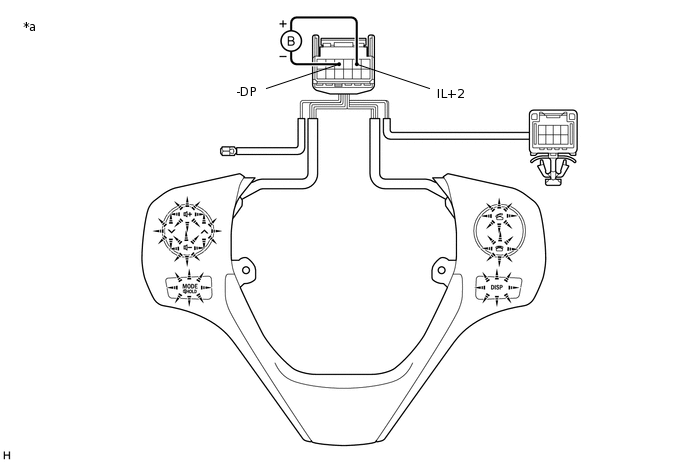
*a
Component without harness connected
(Steering Pad Switch Assembly)
-
-
Connect a positive (+) lead from the battery to terminal 5 (IL+2) and a negative (-) lead to terminal 3 (-DP) of the steering pad switch assembly connector.
Check that the steering pad switch assembly illumination illuminates.
OK
The steering pad switch assembly illumination illuminates.
Tip:If the result is not as specified, replace the steering pad switch assembly.
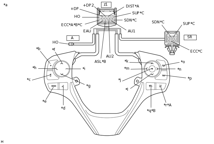
INSPECT STEERING PAD SWITCH ASSEMBLY (for TMUK Made with Back Switch of Steering Pad Switch Assembly)
Measure the resistance according to the value(s) in the table below.
*A
w/ Lane Departure Alert System
*B
w/ Speed Limiter System
*C
w/ Shift Paddle Switch
-
-
*a
Component without harness connected
(Steering Pad Switch Assembly)
*b
Volume+
*c
Volume-
*d
Voice
*e
MODE
*f
Seek+
*g
Seek-
*h
Off hook
*i
On hook
*j
Enter
*k
Up
*l
Down
*m
Left
*n
Right
*o
Back
*p
TRIP
*q
Speed limiter
*r
Lane departure alert
Standard Resistance
Tester Connection
Condition
Specified Condition
z1-1 (HO) - A-1 (HO)
Always
Below 2.5 Ω
z1-11 (AU1) - z1-8 (EAU)
No switch pushed
95 to 105 kΩ
Seek+ switch pushed
Below 2.5 Ω
Seek- switch pushed
313 to 345 Ω
Volume+ switch pushed
950 to 1050 Ω
Volume- switch pushed
2955 to 3265 Ω
z1-10 (AU2) - z1-8 (EAU)
No switch pushed
95 to 105 kΩ
MODE switch pushed
Below 2.5 Ω
On hook switch pushed
313 to 345 Ω
Off hook switch pushed
950 to 1050 Ω
Voice switch pushed
2955 to 3265 Ω
z1-2 (+DP) - z1-8 (EAU)
No switch pushed
95 to 105 kΩ
Enter switch pushed
Below 2.5 Ω
TRIP switch pushed
313 to 345 Ω
Back switch pushed
950 to 1050 Ω
z1-3 (+DP2) - z1-8 (EAU)
No switch pushed
95 to 105 kΩ
Left switch pushed
Below 2.5 Ω
UP switch pushed
313 to 345 Ω
Down switch pushed
950 to 1050 Ω
Right switch pushed
2955 to 3265 Ω
z1-4 (DIST) - z1-7 (ECC)*1
No switch pushed
1 MΩ or higher
Lane departure alert switch pushed
Below 2.5 Ω
z1-9 (ASL) - z1-7 (ECC)*2
No switch pushed
1 MΩ or higher
Speed limiter switch pushed
Below 2.5 Ω
z1-6 (SUP) - SR-2 (SUP)*3
Always
Below 2.5 Ω
z1-7 (ECC) - SR-7 (ECC)*3
Always
Below 2.5 Ω
z1-12 (SDN) - SR-3 (SDN)*3
Always
Below 2.5 Ω
*1: w/ Lane Departure Alert System
*2: w/ Speed Limiter System
*3: w/ Shift Paddle Switch
Tip:If the result is not as specified, replace the steering pad switch assembly.
Check the illumination.
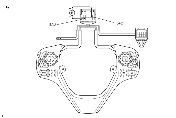
*a
Component without harness connected
(Steering Pad Switch Assembly)
-
-
Connect a positive (+) lead from the battery to terminal 5 (IL+2) and a negative (-) lead to terminal 8 (EAU) of the steering pad switch assembly connector.
Check that the steering pad switch assembly illumination illuminates.
OK
The steering pad switch assembly illumination illuminates.
Tip:If the result is not as specified, replace the steering pad switch assembly.
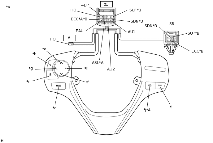
INSPECT STEERING PAD SWITCH ASSEMBLY (for TMUK Made without Back Switch of Steering Pad Switch Assembly)
Measure the resistance according to the value(s) in the table below.
*A
w/ Speed Limiter System
*B
w/ Shift Paddle Switch
*a
Component without harness connected
(Steering Pad Switch Assembly)
*b
Volume+
*c
Volume-
*d
MODE
*e
Seek+
*f
Seek-
*g
Off hook
*h
On hook
*i
DISP
*j
Speed limiter
Standard Resistance
Tester Connection
Condition
Specified Condition
z1-1 (HO) - A-1 (HO)
Always
Below 2.5 Ω
z1-11 (AU1) - z1-8 (EAU)
No switch pushed
95 to 105 kΩ
Seek+ switch pushed
Below 2.5 Ω
Seek- switch pushed
313 to 345 Ω
Volume+ switch pushed
950 to 1050 Ω
Volume- switch pushed
2955 to 3265 Ω
z1-10 (AU2) - z1-8 (EAU)
No switch pushed
95 to 105 kΩ
MODE switch pushed
Below 2.5 Ω
On hook switch pushed
313 to 345 Ω
Off hook switch pushed
950 to 1050 Ω
z1-2 (+DP) - z1-8 (EAU)
No switch pushed
95 to 105 kΩ
DISP switch pushed
Below 2.5 Ω
z1-9 (ASL) - z1-7 (ECC)*1
No switch pushed
1 MΩ or higher
Speed limiter switch pushed
Below 2.5 Ω
z1-6 (SUP) - SR-2 (SUP)*2
Always
Below 2.5 Ω
z1-7 (ECC) - SR-7 (ECC)*2
Always
Below 2.5 Ω
z1-12 (SDN) - SR-3 (SDN)*2
Always
Below 2.5 Ω
*1: w/ Speed Limiter System
*2: w/ Shift Paddle Switch
Tip:If the result is not as specified, replace the steering pad switch assembly.
Check the illumination.
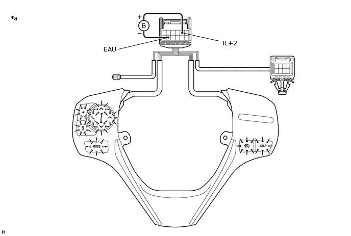
*a
Component without harness connected
(Steering Pad Switch Assembly)
-
-
Connect a positive (+) lead from the battery to terminal 5 (IL+2) and a negative (-) lead to terminal 8 (EAU) of the steering pad switch assembly connector.
Check that the steering pad switch assembly illumination illuminates.
OK
The steering pad switch assembly illumination illuminates.
Tip:If the result is not as specified, replace the steering pad switch assembly.