EASY ACCESS BUCKLE SYSTEM Illumination Circuit
DESCRIPTION
The position control ECU assembly sends buckle illumination signals according to whether the doors are opened/closed and whether the seat belt is fastened/unfastened to the tongue plate.
WIRING DIAGRAM
-
for Driver Side
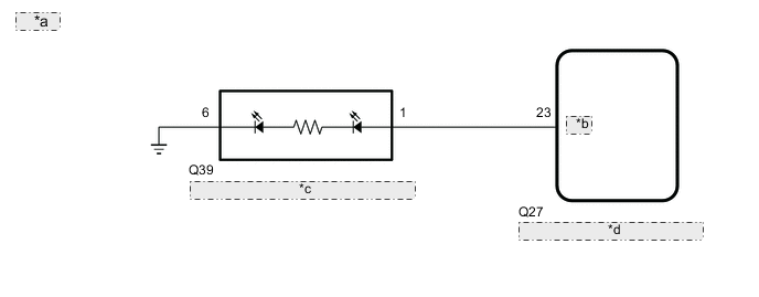
*a for LHD *b BCLL *c Front Seat Inner Belt Assembly LH *d Position Control ECU Assembly 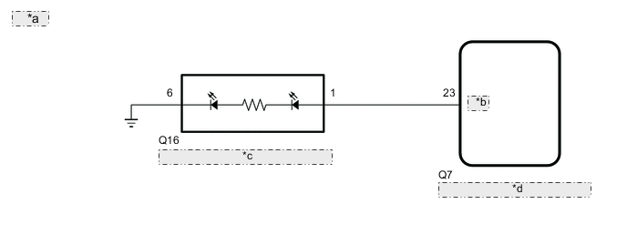
*a for RHD *b BCLL *c Front Seat Inner Belt Assembly RH *d Position Control ECU Assembly -
for Front Passenger Side
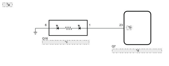
*a for LHD *b BCLL *c Front Seat Inner Belt Assembly RH *d No. 2 Position Control ECU Assembly 
*a for RHD *b BCLL *c Front Seat Inner Belt Assembly LH *d No. 2 Position Control ECU Assembly
CAUTION / NOTICE / HINT
Note
Perform the initialization procedure and stored memory will be reset.
Tech Tips
After replacing the position control ECU assembly, seat assembly and parts (including removal and installation), initialize the position control ECU assembly.
PROCEDURE
-
CHECK PROBLEM SYMPTOMS
Result Result Proceed to for Driver Side A for Front Passenger Side B
B 
CHECK VEHICLE CONDITION Click here
A 
-
CHECK VEHICLE CONDITION
-
Check vehicle condition.
Result Proceed to for LHD for RHD
for RHD
PERFORM ACTIVE TEST USING GTS (BUCKLE LIGHTING) Click here
for LHD
-
-
PERFORM ACTIVE TEST USING GTS (BUCKLE LIGHTING)
-
Connect the GTS to the DLC3.
-
Turn the engine switch on (IG).
-
Turn the GTS on.
-
Enter the following menus: Body Electrical / Driver Seat / Active Test.
-
Perform Active Test according to the display on the GTS.
Body Electrical > Driver Seat > Active TestTester Display Measurement Item Control Range Diagnostic Note Buckle Lighting Perform the Active Test and check that the LED illuminates/turns off. OFF/ON -
Body Electrical > Driver Seat > Active TestTester Display Buckle Lighting OK The buckle illumination illuminates/turns off normally in response to the GTS operation. Result Proceed to OK NG
OK 
REPLACE POSITION CONTROL ECU ASSEMBLY Click here
NG
-
-
INSPECT FRONT SEAT INNER BELT ASSEMBLY LH (BUCKLE ILLUMINATION)
-
Remove the front seat inner belt assembly LH (BUCKLE ILLUMINATION).
-
Inspect the front seat inner belt assembly LH (BUCKLE ILLUMINATION).
Result Proceed to OK NG
NG
REPLACE FRONT SEAT INNER BELT ASSEMBLY LH Click here
OK
-
-
CHECK HARNESS AND CONNECTOR (POSITION CONTROL ECU ASSEMBLY - FRONT SEAT INNER BELT ASSEMBLY LH (BUCKLE ILLUMINATION))
-
Disconnect the Q27 position control ECU assembly connector.
-
Disconnect the Q39 front seat inner belt assembly LH (buckle illumination) connector.
-
Measure the resistance according to the value(s) in the table below.
Standard Resistance Tester Connection Condition Specified Condition Q27-23 (BCLL) - Q39-1 Always Below 1 Ω Q27-23 (BCLL) or Q39-1 - Other terminals and body ground Always 10 kΩ or higher Q39-6 - body ground Always Below 1 Ω Result Proceed to OK NG
OK
REPLACE POSITION CONTROL ECU ASSEMBLY Click here
NG
REPAIR OR REPLACE HARNESS OR CONNECTOR
-
-
PERFORM ACTIVE TEST USING GTS (BUCKLE LIGHTING)
-
Connect the GTS to the DLC3.
-
Turn the engine switch on (IG).
-
Turn the GTS on.
-
Enter the following menus: Body Electrical / Driver Seat / Active Test.
-
Perform Active Test according to the display on the GTS.
Body Electrical > Driver Seat > Active TestTester Display Measurement Item Control Range Diagnostic Note Buckle Lighting Perform the Active Test and check that the LED illuminates/turns off. OFF/ON -
Body Electrical > Driver Seat > Active TestTester Display Buckle Lighting OK The buckle illumination illuminates/turns off normally in response to the GTS operation. Result Proceed to OK NG
OK
REPLACE POSITION CONTROL ECU ASSEMBLY Click here
NG
-
-
INSPECT FRONT SEAT INNER BELT ASSEMBLY RH (BUCKLE ILLUMINATION)
-
Remove the front seat inner belt assembly RH (BUCKLE ILLUMINATION).
-
Inspect the front seat inner belt assembly RH (BUCKLE ILLUMINATION).
Result Proceed to OK NG
NG
REPLACE FRONT SEAT INNER BELT ASSEMBLY RH Click here
OK
-
-
CHECK HARNESS AND CONNECTOR (POSITION CONTROL ECU ASSEMBLY - FRONT SEAT INNER BELT ASSEMBLY RH (BUCKLE ILLUMINATION))
-
Disconnect the Q7 position control ECU assembly connector.
-
Disconnect the Q16 front seat inner belt assembly RH (buckle illumination) connector.
-
Measure the resistance according to the value(s) in the table below.
Standard Resistance Tester Connection Condition Specified Condition Q7-23 (BCLL) - Q16-1 Always Below 1 Ω Q7-23 (BCLL) or Q16-1 - Other terminals and body ground Always 10 kΩ or higher Q16-6 - body ground Always Below 1 Ω Result Proceed to OK NG
OK
REPLACE POSITION CONTROL ECU ASSEMBLY Click here
NG
REPAIR OR REPLACE HARNESS OR CONNECTOR
-
-
CHECK VEHICLE CONDITION
-
Check vehicle condition.
Result Proceed to for LHD for RHD
for RHD
PERFORM ACTIVE TEST USING GTS (BUCKLE LIGHTING) Click here
for LHD
-
-
PERFORM ACTIVE TEST USING GTS (BUCKLE LIGHTING)
-
Connect the GTS to the DLC3.
-
Turn the engine switch on (IG).
-
Turn the GTS on.
-
Enter the following menus: Body Electrical / Passenger Seat / Active Test.
-
Perform Active Test according to the display on the GTS.
Body Electrical > Passenger Seat > Active TestTester Display Measurement Item Control Range Diagnostic Note Buckle Lighting Perform the Active Test and check that the LED illuminates/turns off. OFF/ON -
Body Electrical > Passenger Seat > Active TestTester Display Buckle Lighting OK The buckle illumination illuminates/turns off normally in response to the GTS operation. Result Proceed to OK NG
OK
REPLACE NO. 2 POSITION CONTROL ECU ASSEMBLY Click here
NG
-
-
INSPECT FRONT SEAT INNER BELT ASSEMBLY RH (BUCKLE ILLUMINATION)
-
Remove the front seat inner belt assembly RH (BUCKLE ILLUMINATION).
-
Inspect the front seat inner belt assembly RH (BUCKLE ILLUMINATION).
Result Proceed to OK NG
NG
REPLACE FRONT SEAT INNER BELT ASSEMBLY RH Click here
OK
-
-
CHECK HARNESS AND CONNECTOR (NO. 2 POSITION CONTROL ECU ASSEMBLY - FRONT SEAT INNER BELT ASSEMBLY LH (BUCKLE ILLUMINATION))
-
Disconnect the Q7 No. 2 position control ECU assembly connector.
-
Disconnect the Q16 front seat inner belt assembly RH (buckle illumination) connector.
-
Measure the resistance according to the value(s) in the table below.
Standard Resistance Tester Connection Condition Specified Condition Q7-23 (BCLL) - Q16-1 Always Below 1 Ω Q7-23 (BCLL) or Q16-1 - Other terminals and body ground Always 10 kΩ or higher Q16-6 - body ground Always Below 1 Ω Result Proceed to OK NG
OK
REPLACE NO. 2 POSITION CONTROL ECU ASSEMBLY Click here
NG
REPAIR OR REPLACE HARNESS OR CONNECTOR
-
-
PERFORM ACTIVE TEST USING GTS (BUCKLE LIGHTING)
-
Connect the GTS to the DLC3.
-
Turn the engine switch on (IG).
-
Turn the GTS on.
-
Enter the following menus: Body Electrical / Passenger Seat / Active Test.
-
Perform Active Test according to the display on the GTS.
Body Electrical > Passenger Seat > Active TestTester Display Measurement Item Control Range Diagnostic Note Buckle Lighting Perform the Active Test and check that the LED illuminates/turns off. OFF/ON -
Body Electrical > Passenger Seat > Active TestTester Display Buckle Lighting OK The buckle illumination illuminates/turns off normally in response to the GTS operation. Result Proceed to OK NG
OK
REPLACE NO. 2 POSITION CONTROL ECU ASSEMBLY Click here
NG
-
-
INSPECT FRONT SEAT INNER BELT ASSEMBLY LH (BUCKLE ILLUMINATION)
-
Remove the front seat inner belt assembly LH (BUCKLE ILLUMINATION).
-
Inspect the front seat inner belt assembly LH (BUCKLE ILLUMINATION).
Result Proceed to OK NG
NG
REPLACE FRONT SEAT INNER BELT ASSEMBLY LH Click here
OK
-
-
CHECK HARNESS AND CONNECTOR (NO. 2 POSITION CONTROL ECU ASSEMBLY - FRONT SEAT INNER BELT ASSEMBLY LH (BUCKLE ILLUMINATION))
-
Disconnect the Q27 No. 2 position control ECU assembly connector.
-
Disconnect the Q39 front seat inner belt assembly LH (buckle illumination) connector.
-
Measure the resistance according to the value(s) in the table below.
Standard Resistance Tester Connection Condition Specified Condition Q27-23 (BCLL) - Q39-1 Always Below 1 Ω Q27-23 (BCLL) or Q39-1 - Other terminals and body ground Always 10 kΩ or higher Q39-6 - body ground Always Below 1 Ω Result Proceed to OK NG
OK
REPLACE NO. 2 POSITION CONTROL ECU ASSEMBLY Click here
NG
REPAIR OR REPLACE HARNESS OR CONNECTOR
-