SFI SYSTEM, Diagnostic DTC:P0107 and P0108
| DTC Code | DTC Name |
|---|---|
| P0107 | Manifold Absolute Pressure / Barometric Pressure Circuit Low Input |
| P0108 | Manifold Absolute Pressure / Barometric Pressure Circuit High Input |
DESCRIPTION
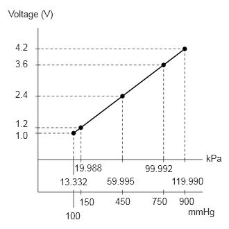
The vacuum sensor uses a built-in sensor to detect pressure inside the intake manifold as an absolute pressure and outputs a voltage. Based on the voltage from the vacuum sensor, the ECM controls the purge VSV and corrects any errors in the air fuel ratio due to changes in pressure.
DTC No. |
DTC Detection Condition |
Trouble Area |
|---|---|---|
P0107 |
The vacuum sensor voltage is below 0.5 V for 0.5 seconds (1 trip detection logic). |
|
P0108 |
The vacuum sensor voltage is higher than 4.5 V for 0.5 seconds (1 trip detection logic). |
|
When any of these DTCs are output, check the manifold absolute pressure using the GTS. Enter the following menus: Powertrain / Engine and ECT / Data List / MAP.
MAP |
Malfunction |
|---|---|
Approximately 0 kPa |
|
130 kPa or higher |
|
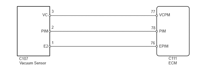
WIRING DIAGRAM
CAUTION / NOTICE / HINT
Read freeze frame data using the GTS. The ECM records vehicle and driving condition information as freeze frame data the moment a DTC is stored. When troubleshooting, freeze frame data can help determine if the vehicle was moving or stationary, if the engine was warmed up or not, if the air fuel ratio was lean or rich, and other data from the time the malfunction occurred.
PROCEDURE
READ VALUE USING GTS (MANIFOLD ABSOLUTE PRESSURE)
Connect the GTS to the DLC3.
Turn the ignition switch to ON.
Turn the GTS on.
Enter the following menus: Powertrain / Engine and ECT / Data List / MAP.
Read the MAP value.
Table 1. Result Result
Proceed to
0 kPa
A
130 kPa or higher
B
Approximately same as atmospheric pressure
C
READ VALUE USING GTS (MANIFOLD ABSOLUTE PRESSURE)
Connect the GTS to the DLC3.
-
Disconnect the vacuum sensor connector.
Turn the ignition switch to ON.
Turn the GTS on.
Enter the following menus: Powertrain / Engine and ECT / Data List / MAP.
Check how the "MAP" displayed on the GTS changes compared to the value measured before disconnecting the connector of the vacuum sensor.
Table 2. Result Result
Proceed to
Changes (From approximately 0 kPa (0 mmHg, 0 in.Hg) to a value of 130 kPa (975 mmHg, 38.4 in.Hg) or higher)
A
Does not change (Approximately 0 kPa (0 mmHg, 0 in.Hg))
B
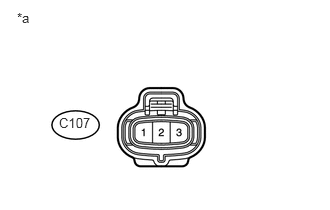
Table 3. Text in Illustration *a
Front view of wire harness connector
(to Vacuum Sensor)
Reconnect the vacuum sensor connector.
CHECK HARNESS AND CONNECTOR (VACUUM SENSOR - ECM)Click here
CHECK VACUUM SENSOR (POWER SOURCE)
-
Disconnect the vacuum sensor connector.
Measure the voltage according to the value(s) in the table below.
Standard Voltage
Tester Connection
Switch Condition
Specified Condition
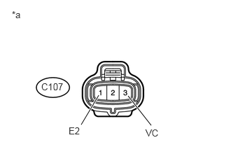
C107-3 (VC) - C107-1 (E2)
Ignition switch ON
4.5 to 5.5 V
Table 4. Text in Illustration *a
Front view of wire harness connector
(to Vacuum Sensor)
Reconnect the vacuum sensor connector.
CHECK HARNESS AND CONNECTOR (VACUUM SENSOR - ECM)Click here
-
CHECK HARNESS AND CONNECTOR (VACUUM SENSOR - ECM)
Disconnect the vacuum sensor connector.
Disconnect the ECM connector.
Measure the resistance according to the value(s) in the table below.
Standard Resistance (Check for Open)
Tester Connection
Condition
Specified Condition
C107-2 (PIM) - C111-78 (PIM)
Always
Below 1 Ω
Standard Resistance (Check for Short)
Tester Connection
Condition
Specified Condition
C107-2 (PIM) or C111-78 (PIM) - Body ground
Always
10 kΩ or higher
Reconnect the ECM connector.
Reconnect the vacuum sensor connector.
REPAIR OR REPLACE HARNESS OR CONNECTOR (VACUUM SENSOR - ECM)
REPLACE VACUUM SENSOR
Replace the vacuum sensor (Click here).
CHECK WHETHER DTC OUTPUT RECURS
Connect the GTS to the DLC3.
Clear the DTCs (Click here).
Turn the ignition switch off.
Turn the ignition switch to ON and turn the GTS on.
After the engine is started, race the engine for 1 second.
Enter the following menus: Powertrain / Engine and ECT / Trouble Codes.
Read the DTCs.
Table 5. Result Display (DTC output)
Proceed to
No DTC is output
A
DTC P0107 or P0108 is output
B
END
CHECK HARNESS AND CONNECTOR (VACUUM SENSOR - ECM)
Disconnect the vacuum sensor connector.
Disconnect the ECM connector.
Measure the resistance according to the value(s) in the table below.
Standard Resistance (Check for Open)
Tester Connection
Condition
Specified Condition
C107-2 (PIM) - C111-78 (PIM)
Always
Below 1 Ω
C107-3 (VC) - C111-77 (VCPM)
Always
Below 1 Ω
C107-1 (E2) - C111-76 (EPIM)
Always
Below 1 Ω
Standard Resistance (Check for Short)
Tester Connection
Condition
Specified Condition
C107-2 (PIM) or C111-78 (PIM) - Body ground
Always
10 kΩ or higher
C107-3 (VC) or C111-77 (VCPM) - Body ground
Always
10 kΩ or higher
Reconnect the ECM connector.
Reconnect the vacuum sensor connector.
REPAIR OR REPLACE HARNESS OR CONNECTOR (VACUUM SENSOR - ECM)