AIR PUMP(w/ Secondary Air Injection System) INSTALLATION
PROCEDURE
-
INSTALL AIR PUMP ASSEMBLY
-
Attach the 3 fittings of the air pump insulators to install the air pump assembly to the air pump bracket.
-
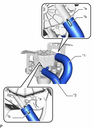
*1 No. 2 Air Injection System Hose *2 No. 3 Air Injection System Hose *a Rib *b Paint Mark Connect the No. 2 air injection system hose so that its paint mark aligns with the rib of the air pump assembly as shown in the illustration.
Tech Tips
Make sure the paint mark of the No. 2 air injection system hose is facing upward.
-
Connect the No. 3 air injection system hose so that its paint mark aligns with the rib of the air pump assembly as shown in the illustration.
Tech Tips
Make sure the paint mark of the No. 3 air injection system hose is facing upward.
-
Slide the clip to secure the No. 3 air injection system hose.
-
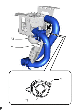
*1 No. 3 Air Injection System Hose *2 Wire Harness *3 Hose Clamp Install the hose clamp to the No. 3 air injection system hose and wire harness as shown in the illustration.
-
-
INSTALL AIR PUMP INLET PIPE
-
Install the air pump inlet pipe to the body panel with the 2 bolts.
- Torque:
- 6.0 N*m { 61 kgf*cm, 53 in.*lbf }
-
-
INSTALL AIR PUMP ASSEMBLY WITH BRACKET
-
Install the air pump assembly with bracket to the body panel with the 3 bolts.
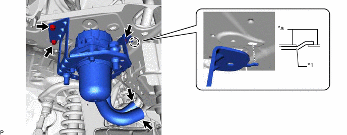
*1 Air Pump Bracket - - *a Body Panel - - - Torque:
- 8.0 N*m { 82 kgf*cm, 71 in.*lbf }
Tech Tips
Insert the protrusion of the air pump bracket into the hole in the body.
-
Connect the No. 3 air injection system hose to the air pump inlet pipe, and slide the clip to secure the hose.
-
Connect the No. 2 air injection system hose to the air pump inlet pipe.
-
Attach the clamp and connect the wire harness.
-
Connect the air pump connector.
-
-
INSTALL NO. 4 AIR INJECTION SYSTEM HOSE
-
Connect the No. 4 air injection system hose to the air switching valve assembly and air pump inlet pipe, and slide the 2 clips to secure the hoses.
-
Install the hose clamp to the No. 4 air injection system hose and radiator hose inlet.
-
-
INSTALL AIR PUMP INLET
-
Install the air pump inlet to the No. 1 air injection system hose.
-
Install the No. 1 air injection system hose to the air pump inlet pipe.
-
Connect the air pump inlet with the bolt.
- Torque:
- 6.0 N*m { 61 kgf*cm, 53 in.*lbf }
-
-
INSTALL AIR CLEANER CASE SUB-ASSEMBLY
-
INSTALL AIR CLEANER FILTER ELEMENT SUB-ASSEMBLY
-
INSTALL AIR CLEANER CAP SUB-ASSEMBLY WITH NO. 1 AIR CLEANER HOSE
-
CONNECT FRONT FENDER LINER RH
-
Connect the front fender liner RH to the front bumper cover and body panel with the 6 clips and 3 screws.
-
-
INSTALL FRONT UPPER FENDER APRON SEAL RH