INPUT SHAFT REASSEMBLY

PROCEDURE
-
INSTALL FRONT INPUT SHAFT BEARING
-
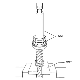
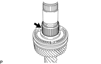
Using SST and a press, install a new front input shaft bearing to the manual transmission case sub-assembly.
- SST
- 09316-60011 ( 09316-00011, 09316-00061 )
- 09527-20011
-
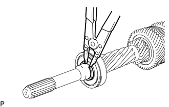
Select a new snap ring that will allow minimal axial play.
Standard clearance 0.1 mm (0.00394 in.) or less Standard Snap Ring Part No. Mark Thickness 90520-T0142 A 2.65 to 2.70 mm (0.1044 to 0.1062 in.) 90520-T0143 B 2.70 to 2.75 mm (0.1063 to 0.1082 in.) 90520-T0144 C 2.75 to 2.80 mm (0.1083 to 0.1102 in.) 90520-T0145 D 2.80 to 2.85 mm (0.1103 to 0.1122 in.) 90520-T0146 E 2.85 to 2.90 mm (0.1122 to 0.1141 in.) 90520-T0147 F 2.90 to 2.95 mm (0.1142 to 0.1161 in.) -
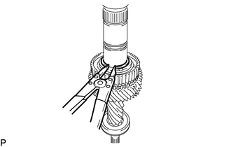
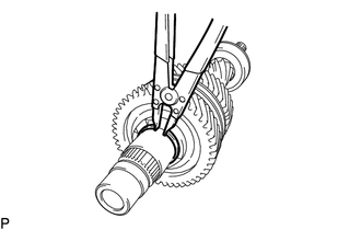
Using a snap ring expander, install the snap ring to the input shaft.
-
-
INSTALL 5TH GEAR NEEDLE ROLLER BEARING
-
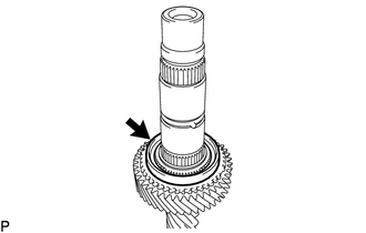
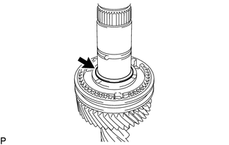
Coat the 5th gear needle roller bearing with gear oil and install it to the input shaft.
-
-
INSTALL 5TH GEAR
-
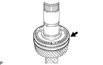
Coat the 5th gear with gear oil and install it to the input shaft.
-
-
INSTALL NO. 3 SYNCHRONIZER RING
-
Coat the No. 3 synchronizer ring with gear oil, and then install it to the input shaft.
-
-
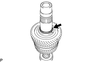
INSTALL NO. 3 TRANSMISSION CLUTCH HUB
-
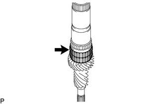
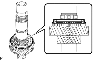
*1 Protrusion of the No. 3 Synchronizer Ring *2 Groove of the No. 3 Transmission Clutch Hub Using SST and press, install the No. 3 transmission clutch hub to the input shaft.
- SST
- 09308-14010
Note
Align the protrusion of the No. 3 synchronizer ring with the groove of the No. 3 transmission clutch hub as shown in the illustration
-
-
INSTALL CLUTCH HUB SET SHAFT SNAP RING
-
Select a new clutch hub set shaft snap ring that will allow minimal axial play.
Standard clearance 0.1 mm (0.00394 in.) or less Standard Snap Ring Part No. Mark Thickness 90520-T0148 A 1.80 to 1.85 mm (0.0709 to 0.0728 in.) 90520-T0149 B 1.85 to 1.90 mm (0.0729 to 0.0748 in.) 90520-T0150 C 1.90 to 1.95 mm (0.0749 to 0.0767 in.) 90520-T0151 D 1.95 to 2.00 mm (0.0768 to 0.0787 in.) 90520-T0152 E 2.00 to 2.05 mm (0.0788 to 0.0807 in.) 90520-T0153 F 2.05 to 2.10 mm (0.0808 to 0.0826 in.) -
Using a snap ring expander, install the clutch hub set shaft snap ring to the input shaft.
-
-
INSTALL NO. 1 SYNCHROMESH SHIFTING KEY
-
Install the 3 No. 1 synchromesh shifting keys to the No. 3 transmission clutch hub.
-
-
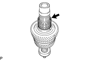
INSTALL NO. 2 TRANSMISSION HUB SLEEVE
-
Apply a light coat of gear oil to the sleeve and hub.
-
Install the No. 2 transmission hub sleeve to the No. 3 transmission clutch hub.
-
-
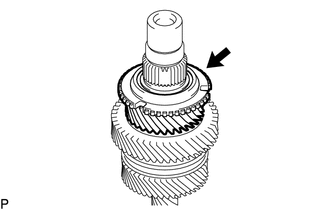
INSTALL 6TH GEAR SPACER
-
Coat the 6th gear spacer with gear oil, and then install it to the input shaft.
-
-
INSTALL 6TH GEAR NEEDLE ROLLER BEARING
-
Coat the 6th gear needle roller bearing with gear oil, and then install it to the input shaft.
-
-
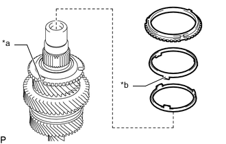
INSTALL NO. 3 SYNCHRONIZER RING
-
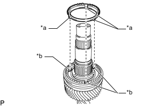
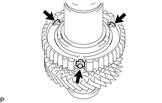
*a Protrusion *b Groove Coat the No. 3 synchronizer ring with gear oil, and then install it to the No. 3 transmission clutch hub.
Note
Align the protrusion of the No. 3 synchronizer ring with the groove of the No. 3 transmission clutch hub.
-
-
INSTALL 6TH GEAR SUB-ASSEMBLY
-
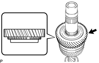
Coat the 6th gear sub-assembly with gear oil, and then install it to the input shaft.
Tech Tips
Make sure that the 6th gear sub-assembly faces the correct direction as shown in the illustration.
-
Check that the 6th gear sub-assembly and No. 3 synchronizer ring move smoothly.
-
-
INSTALL GEAR THRUST WASHER STRAIGHT PIN
-
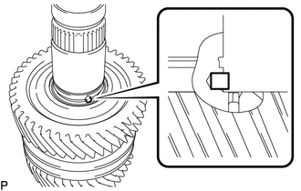
Install the gear thrust washer straight pin to the input shaft.
-
-
INSTALL 3RD GEAR THRUST WASHER
-
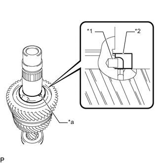
*1 Gear Thrust Washer Straight Pin *2 3rd Gear Thrust Washer *a Groove Coat the 3rd gear thrust washer with gear oil and install it to the input shaft.
Tech Tips
Align the groove of the 3rd gear thrust washer with the gear thrust washer straight pin.
-
-
INSTALL GEAR THRUST WASHER SHAFT SNAP RING
-
Select a new gear thrust washer shaft snap ring that will allow minimal axial play.
Standard clearance 0.1 mm (0.00394 in.) or less Standard Snap Ring Part No. Mark Thickness 90520-T0155 A 2.07 to 2.12 mm (0.0815 to 0.0834 in.) 90520-T0156 B 2.12 to 2.17 mm (0.0835 to 0.0854 in.) 90520-T0157 C 2.17 to 2.22 mm (0.0855 to 0.0874 in.) 90520-T0158 D 2.22 to 2.27 mm (0.0875 to 0.0893 in.) 90520-T0159 E 2.27 to 2.32 mm (0.0894 to 0.0913 in.) 90520-T0160 F 2.32 to 2.37 mm (0.0914 to 0.0933 in.) -
Using a snap ring expander, install the gear thrust washer shaft snap ring to the input shaft.
-
-
INSTALL 3RD GEAR SPACER
-
Coat the 3rd gear spacer with gear oil and install it to the input shaft.
-
-
INSTALL 3RD GEAR NEEDLE ROLLER BEARING
-
Coat the 3rd gear needle roller bearing with gear oil, and then install it to the input shaft.
-
-
INSTALL 3RD GEAR
-
Coat the 3rd gear with gear oil, and then install it to the input shaft.
-
-
INSTALL NO. 3 SYNCHRONIZER RING SET
-
*a Groove *b Protrusion Coat the No. 3 synchronizer ring set with gear oil, and then install it to the input shaft.
Note
Align the protrusion of the No. 3 synchronizer ring set with the groove of the 3rd gear.
-
-
INSTALL NO. 2 TRANSMISSION CLUTCH HUB
-
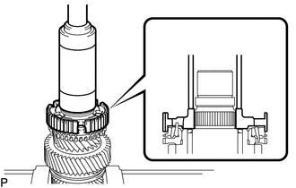
Using SST, set the input shaft
- SST
- 09527-20011
-
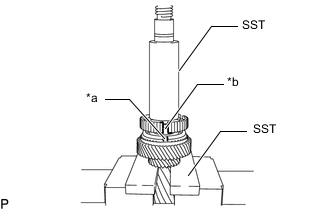
Using SST and a press, install the No. 2 transmission clutch hub to the input shaft.
-
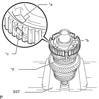
*a Hole of the No. 2 transmission Clutch Hub *b Groove of the No. 2 transmission Clutch Hub *c Protrusion of the No. 3 Synchronizer Ring (middle ring) *d Protrusion of the No. 3 Synchronizer Ring Install the No. 2 transmission clutch hub to the input shaft.
Tech Tips
-
Align the protrusion of the No. 3 synchronizer ring set (middle ring) with the hole of the No. 2 transmission clutch hub as shown in the illustration
-
Align the protrusion of the No. 2 synchronizer ring set with the groove of the No. 2 transmission clutch hub as shown in the illustration
-
-
Using SST and a press, install the No. 3 transmission clutch hub to the input shaft.
- SST
- 09527-20011
-
-
INSTALL NO. 1 SYNCHROMESH SHIFTING KEY
-
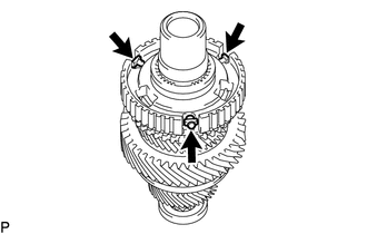
Install the 3 No. 1 synchromesh shifting keys to the No. 2 transmission clutch hub.
-
-
INSTALL NO. 2 TRANSMISSION HUB SLEEVE
-
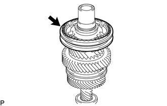
Apply a light coat of gear oil to the sleeve and hub.
-
Install the No. 2 transmission hub sleeve to the No. 2 transmission clutch hub.
-
-
INSTALL NO. 2 CLUTCH HUB SETTING SHAFT SNAP RING
-

Select a new No. 2 clutch hub setting shaft snap ring that will allow minimal axial play.
Standard clearance 0.1 mm (0.00394 in.) or less Standard Snap Ring Part No. Mark Thickness 90520-T0161 A 2.50 to 2.55 mm (0.0983 to 0.1004 in.) 90520-T0162 B 2.55 to 2.60 mm (0.1004 to 0.1023 in.) 90520-T0163 C 2.60 to 2.65 mm (0.1024 to 0.1043 in.) 90520-T0164 D 2.65 to 2.70 mm (0.1044 to 0.1062 in.) 90520-T0165 E 2.70 to 2.75 mm (0.1063 to 0.1082 in.) 90520-T0166 F 2.75 to 2.80 mm (0.1083 to 0.1102 in.) -
Using a brass bar and hammer, install the No. 2 clutch hub setting shaft snap ring to the input shaft.
-
-
INSPECT 3RD GEAR THRUST CLEARANCE
-
INSPECT 3RD GEAR RADIAL CLEARANCE
-
INSPECT 6TH GEAR SUB-ASSEMBLY THRUST CLEARANCE
-
INSPECT 6TH GEAR SUB-ASSEMBLY RADIAL CLEARANCE
-
INSPECT 5TH GEAR THRUST CLEARANCE
-
INSPECT 5TH GEAR RADIAL CLEARANCE