THEFT DETERRENT SYSTEM Door Courtesy Switch Circuit
DESCRIPTION
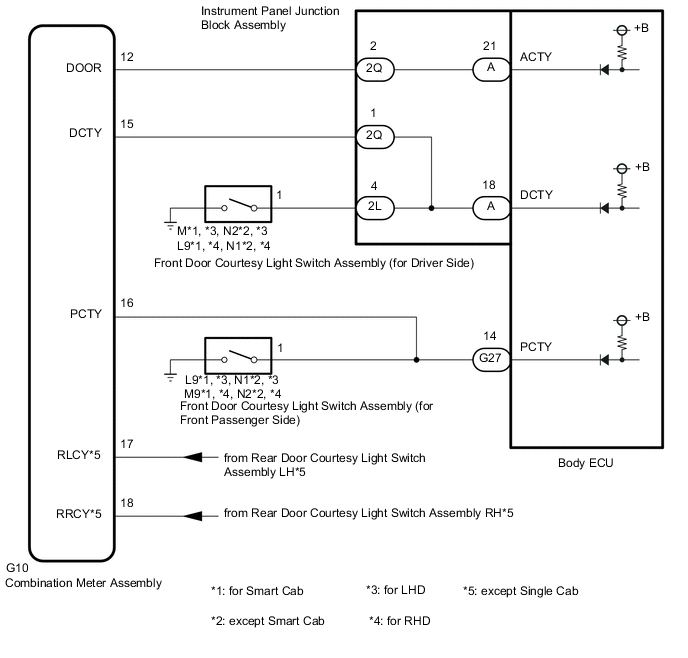
The theft body ECU receives a door open or closed signal from front door courtesy light switch and combination meter assembly.
WIRING DIAGRAM
CAUTION / NOTICE / HINT
Note
-
w/ Door Control Battery:
As the door control battery is installed between the vehicle battery and body ECU, first perform the inspections to confirm that there are no malfunctions in the power source circuit for the body ECU before performing this troubleshooting procedure.
-
w/ Automatic Light Control System:
If the body ECU has been replaced, it is necessary to initialize the body ECU.
PROCEDURE
-
CHECK METER / GAUGE SYSTEM
-
Check the meter / gauge system (door courtesy switch) is functioning normally.
Result Result OK NG
NG 
GO TO METER / GAUGE SYSTEM Click here
OK 
-
-
CHECK FRONT DOOR COURTESY SWITCH CIRCUIT
-
Remove the body ECU.
-
for LHD:
-
for RHD:
-
-
Connect the instrument panel junction block assembly connector.
-
Disconnect the G10 combination meter assembly connector.
-
Measure the resistance according to the value(s) in the table below.
Standard Resistance Tester Connection Condition Specified Condition A-18 (DCTY) - Body ground Driver side door closed (OFF) → Open (ON) 10 kΩ or higher → Below 1 Ω G27-14 (PCTY) - Body ground Front passenger side door closed (OFF) → Open (ON) 10 kΩ or higher → Below 1 Ω Result Proceed to OK NG (for Driver Side, LHD) NG (for Driver Side, RHD) NG (for Front Passenger Side)
NG (for Driver Side, LHD)
REPLACE INSTRUMENT PANEL JUNCTION BLOCK ASSEMBLY Click here
NG (for Driver Side, RHD)
REPLACE INSTRUMENT PANEL JUNCTION BLOCK ASSEMBLY Click here
NG (for Front Passenger Side)
REPAIR OR REPLACE HARNESS OR CONNECTOR
OK
-
-
CHECK DOOR COURTESY SWITCH SIGNAL (ACTY)
-
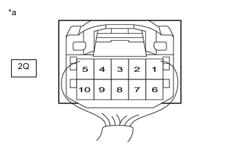
*a Component with harness connected
(Instrument Panel Junction Block Assembly)
Measure the voltage according to the value(s) in the table below.
Standard Voltage Tester Connection Condition Specified Condition 2Q-2 - Body ground All doors closed except driver door → Any door open except driver door 11 to 14 V → Below 1 V Result Proceed to OK NG
OK
PROCEED TO NEXT SUSPECTED AREA SHOWN IN PROBLEM SYMPTOMS TABLE Click here
NG
-
-
CHECK HARNESS AND CONNECTOR (COMBINATION METER ASSEMBLY - BODY ECU)
-
Remove the body ECU.
-
for LHD:
-
for RHD:
-
-
Connect the instrument panel junction block assembly connectors.
-
Disconnect the G10 combination meter assembly connector.
-
Measure the resistance according to the value(s) in the table below.
Standard Resistance Tester Connection Condition Specified Condition G10-12 (DOOR) - A-21 (ACTY) Always Below 1 Ω G10-12 (DOOR) - Body ground Always 10 kΩ or higher Result Result OK NG
NG 
CHECK HARNESS AND CONNECTOR (COMBINATION METER ASSEMBLY - INSTRUMENT PANEL JUNCTION BLOCK ASSEMBLY) Click here
OK
-
-
CHECK BODY ECU
-
Disconnect the combination meter assembly connector.
-
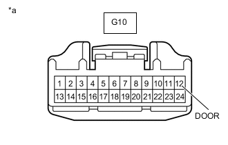
*a Front view of wire harness connector
(to Combination Meter Assembly)
Measure the voltage according to the value(s) in the table below.
Standard Voltage Tester Connection Condition Specified Condition G10-12 (DOOR) - Body ground Always 11 to 14 V Result Proceed to OK NG (for LHD) NG (for RHD)
OK
REPLACE COMBINATION METER ASSEMBLY Click here
NG (for LHD)
REPLACE BODY ECU Click here
NG (for RHD)
REPLACE BODY ECU Click here
-
-
CHECK HARNESS AND CONNECTOR (COMBINATION METER ASSEMBLY - INSTRUMENT PANEL JUNCTION BLOCK ASSEMBLY)
-
Disconnect the 2Q instrument panel junction block assembly connector.
-
Disconnect the G10 combination meter assembly connector.
-
Measure the resistance according to the value(s) in the table below.
Standard Resistance Tester Connection Condition Specified Condition G10-12 (DOOR) - 2Q-2 Always Below 1 Ω G10-12 (DOOR) - Body ground Always 10 kΩ or higher Result Result OK (for LHD) OK (for RHD) NG
OK (for LHD)
REPLACE INSTRUMENT PANEL JUNCTION BLOCK ASSEMBLY Click here
OK (for RHD)
REPLACE INSTRUMENT PANEL JUNCTION BLOCK ASSEMBLY Click here
NG
REPAIR OR REPLACE HARNESS OR CONNECTOR
-