CANISTER(w/ Canister Pump Module) INSTALLATION
PROCEDURE
-
INSTALL LEAK DETECTION PUMP SUB-ASSEMBLY
Tech Tips
Only perform this procedure when replacement of the leak detection pump sub-assembly is necessary.
-
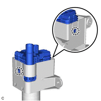
Engage the 2 claws to install a new leak detection pump sub-assembly to the No. 2 charcoal canister sub-assembly.
Note
-
Do not allow foreign matter such as grease, oil or water to adhere to the O-ring.
-
Ensure that the claws are engaged properly.
-
-
-
INSTALL NO. 2 CHARCOAL CANISTER SUB-ASSEMBLY
-
Remove the rear suspension member sub-assembly.
-
Install the No. 2 charcoal canister sub-assembly to the vehicle body with the 3 nuts.
- Torque:
- 8.0 N*m { 82 kgf*cm, 71 in.*lbf }
-
Connect the leak detection pump sub-assembly connector.
-
Push in the air line tube to the pipe (leak detection pump sub-assembly) until the air line tube makes a "click" sound.
Note
-
Check that there are no scratches or foreign matter around the connecting parts of the tube connector and pipe (leak detection pump sub-assembly) before performing this work.
-
After connecting the air line tube, check that the air line tube is securely connected by pulling on the tube connector.
-
-
Install the rear suspension member sub-assembly.
-
-
INSTALL CANISTER (CHARCOAL CANISTER ASSEMBLY)
-
Install the clip to the vehicle body.
-
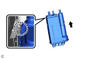
Engage the claw to install the canister (charcoal canister assembly) to the vehicle body as shown in the illustration.
-
Engage the clip to the canister (charcoal canister assembly).
-
Install the 2 bolts.
- Torque:
- 8.0 N*m { 82 kgf*cm, 71 in.*lbf }
-
Connect the purge line hose to the canister (charcoal canister assembly) and slide the clip to secure it.
-
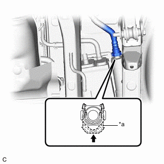
*a Retainer 
Push in Push the vent line hose onto the canister (charcoal canister assembly) and push in the retainer to engage the lock claws.
Note
-
Check that there are no scratches or foreign matter around the connecting parts of the tube connector and pipe (canister (charcoal canister assembly)) before performing this work.
-
After connecting the vent line hose, check that the vent line hose is securely connected by pulling on the tube connector.
-
-
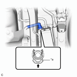
*a Retainer Push in Push the fuel tank vent hose onto the canister (charcoal canister assembly) and push in the retainer to engage the lock claws.
Note
-
Check that there are no scratches or foreign matter around the connecting parts of the tube connector and pipe (canister (charcoal canister assembly)) before performing this work.
-
After connecting the fuel tank vent hose, check that the fuel tank vent hose is securely connected by pulling on the tube connector.
-
-
-
INSTALL REAR NO. 1 STABILIZER BAR BRACKET
-
Install the 2 rear No. 1 stabilizer bar brackets to the vehicle body with the 4 bolts.
- Torque:
- 78 N*m { 795 kgf*cm, 58 ft.*lbf }
-
-
INSTALL CENTER EXHAUST PIPE ASSEMBLY
-
Install 2 new gaskets to the front exhaust pipe assembly (TWC: Rear Catalyst) and center exhaust pipe assembly.
-
Connect the center exhaust pipe assembly to the exhaust pipe support.
-
Install the center exhaust pipe assembly to the front exhaust pipe assembly (TWC: Rear Catalyst) and tail exhaust pipe assembly with 4 new bolts.
- Torque:
- 43 N*m { 438 kgf*cm, 32 ft.*lbf }
-
-
INSPECT FOR EXHAUST GAS LEAK