SFI SYSTEM(w/ Canister Pump Module), Diagnostic DTC:P070513, P070562
| DTC Code | DTC Name |
|---|---|
| P070513 | Transmission Range Sensor "A" Circuit Open |
| P070562 | Transmission Range Sensor "A" Signal Compare Failure |
DESCRIPTION
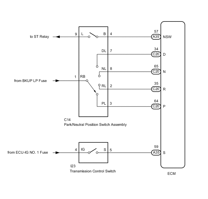
The park/neutral position switch assembly detects the shift lever position and sends signals to the ECM.
| DTC No. | Detection Item | DTC Detection Condition | Trouble Area | MIL | Memory | Note |
|---|---|---|---|---|---|---|
| P070513 | Transmission Range Sensor "A" Circuit Open | All switches are off simultaneously for NSW, P, R, N and D for 1 minute or more. |
|
Comes on | DTC stored | SAE: P0705 |
| P070562 | Transmission Range Sensor "A" Signal Compare Failure | Both of the following conditions A or B is met (2 trip detection logic): A. One of the following conditions (a), (b) or (c) is met for 2 seconds or more: (a) Any 2 or more of the following signals are on simultaneously:
(b) Any 2 or more of the following signals are on simultaneously:
(c) Any 2 or more of the following signals are on simultaneously:
B. Any of the following conditions is met for 2 seconds or more in the M position:
|
|
Comes on | DTC stored | SAE: P0705 |
MONITOR DESCRIPTION
These DTCs indicate a problem with the park/neutral position switch assembly and the wire harness in the park/neutral position switch assembly circuit.
The park/neutral position switch assembly detects the shift lever position and sends a signal to the ECM.
For security, the park/neutral position switch assembly detects the shift lever position so that the engine can be started only when the shift lever is in P or N.
The park/neutral position switch assembly sends a signal to the ECM according to the shift lever position (P, R, N, D, or M). The ECM determines that there is a problem with the switch or related parts if it receives more than 1 position signal simultaneously. The ECM will illuminate the MIL and store this DTC.
MONITOR STRATEGY
| Required Sensors/Components | Park/Neutral position switch assembly |
| Frequency of Operation | Continuous |
CONFIRMATION DRIVING PATTERN
-
Connect the GTS to the DLC3.
-
Turn the engine switch on (IG) and turn the GTS on.
-
Clear the DTCs (even if no DTCs are stored, perform the clear DTC procedure).
-
Turn the engine switch off and wait for at least 30 seconds.
-
Turn the engine switch on (IG) and turn the GTS on.
-
Move the shift lever to R and wait 2 seconds or more.
-
Move the shift lever to N and wait 2 seconds or more.
-
Move the shift lever to D and wait 2 seconds or more.
-
Move the shift lever to M and wait 2 seconds or more.
-
Move the shift lever to P and wait 2 seconds or more.
-
Wait 1 minute or more.
-
Enter the following menus: Powertrain / Engine / Trouble Codes.
-
Read the pending DTCs.
Tech Tips
-
If a pending DTC is output, the system is malfunctioning.
-
If a pending DTC is not output, perform the following procedure.
-
-
Enter the following menus: Powertrain / Engine / Utility / All Readiness.
-
Input the DTC: P070513 or P070562.
-
Check the DTC judgment result.
GTS Display Description NORMAL
-
DTC judgment completed
-
System normal
ABNORMAL
-
DTC judgment completed
-
System abnormal
INCOMPLETE
-
DTC judgment not completed
-
Perform driving pattern after confirming DTC enabling conditions
N/A
-
Unable to perform DTC judgment
-
Number of DTCs which do not fulfill DTC preconditions has reached ECU's memory limit
Tech Tips
-
If the judgment result shows NORMAL, the system is normal.
-
If the judgment result shows ABNORMAL, the system has a malfunction.
-
WIRING DIAGRAM
CAUTION / NOTICE / HINT
Note
Inspect the fuses for circuits related to this system before performing the following procedure.
Tech Tips
Using the GTS to read the Data List allows the values or states of switches, sensors, actuators and other items to be read without removing any parts. This non-intrusive inspection can be very useful because intermittent conditions or signals may be discovered before parts or wiring is disturbed. Reading the Data List information early in troubleshooting is one way to save diagnostic time.
-
DATA LIST
Note
In the table below, the values listed under "Normal Condition" are reference values. Do not depend solely on these reference values when deciding whether a part is faulty or not.
-
Warm up the engine.
-
Turn the engine switch off.
-
Connect the GTS to the DLC3.
-
Turn the engine switch on (IG).
-
Turn the GTS on.
-
Enter the following menus: Powertrain / Engine / Data List / AT / Shift SW Status (P Range), Shift SW Status (R Range), Shift SW Status (N Range), Shift SW Status (D Range) and Shift SW Status (S Range).
Powertrain > Engine > Data ListTester Display Shift SW Status (P Range) Shift SW Status (R Range) Shift SW Status (N Range) Sports Mode Selection SW Shift SW Status (D Range) -
Read the values displayed on the GTS.
GTS Display Measurement Item/Range Normal Condition Diagnostic Note Shift SW Status (R Range) Park/Neutral position switch assembly status:
ON or OFF
-
ON: Shift lever in R
-
OFF: Shift lever not in R
- Shift SW Status (P Range) Park/Neutral position switch assembly status:
ON or OFF
-
ON: Shift lever in P
-
OFF: Shift lever not in P
- Shift SW Status (N Range) Park/Neutral position switch assembly status:
ON or OFF
-
ON: Shift lever in N
-
OFF: Shift lever not in N
- Shift SW Status (D Range) Park/Neutral position switch assembly status:
ON or OFF
-
ON: Shift lever in D or M
-
OFF: Shift lever not in D or M
- Shift SW Status (S Range) Transmission control switch status:
ON or OFF
-
ON: Shift lever in M
-
OFF: Shift lever not in M
- -
-
PROCEDURE
-
CHECK HARNESS AND CONNECTOR (POWER SOURCE OF PARK/NEUTRAL POSITION SWITCH ASSEMBLY)
-
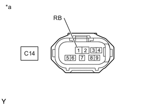
*a Front view of wire harness connector
(to Park/Neutral Position Switch Assembly)
Disconnect the park/neutral position switch assembly connector.
-
Measure the voltage according to the value(s) in the table below.
Standard Voltage Tester Connection Switch Condition Specified Condition C14-1 (RB) - Body ground Engine switch on (IG) 11 to 14 V Engine switch off Below 1 V Result Proceed to OK NG
NG 
REPAIR OR REPLACE HARNESS OR CONNECTOR
OK 
-
-
CHECK HARNESS AND CONNECTOR (NSW TERMINAL VOLTAGE)
-
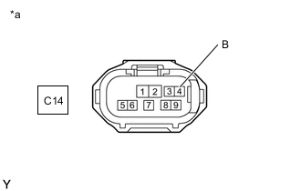
*a Front view of wire harness connector
(to Park/Neutral Position Switch Assembly)
Measure the voltage according to the value(s) in the table below.
Standard Voltage Tester Connection Switch Condition Specified Condition C14-4 (B) - Body ground Engine switch on (IG) 11 to 14 V Engine switch off Below 1 V Result Proceed to OK NG
NG 
CHECK HARNESS AND CONNECTOR (PARK/NEUTRAL POSITION SWITCH ASSEMBLY - ECM) Click here
OK
-
-
INSPECT PARK/NEUTRAL POSITION SWITCH ASSEMBLY
-
Inspect the park/neutral position switch assembly.
for 2WD: Click here
for AWD: Click here
Result Proceed to OK NG
NG
REPLACE PARK/NEUTRAL POSITION SWITCH ASSEMBLY for 2WD: Click here
REPLACE PARK/NEUTRAL POSITION SWITCH ASSEMBLY for AWD: Click hereOK
-
-
CHECK HARNESS AND CONNECTOR (POWER SOURCE OF TRANSMISSION CONTROL SWITCH)
-
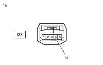
*a Front view of wire harness connector
(to Transmission Control Switch)
Connect the park/neutral position switch assembly connector.
-
Disconnect the transmission control switch connector.
-
Measure the voltage according to the value(s) in the table below.
Standard Voltage Tester Connection Switch Condition Specified Condition I23-4 (IG) - Body ground Engine switch on (IG) 11 to 14 V Engine switch off Below 1 V Result Proceed to OK NG
NG
REPAIR OR REPLACE HARNESS OR CONNECTOR
OK
-
-
INSPECT TRANSMISSION CONTROL SWITCH (SHIFT LEVER ASSEMBLY)
-
Inspect the transmission control switch.
for 2WD: Click here
for AWD: Click here
Result Proceed to OK NG
NG
REPLACE TRANSMISSION CONTROL SWITCH (SHIFT LEVER ASSEMBLY) for 2WD: Click here
REPLACE TRANSMISSION CONTROL SWITCH (SHIFT LEVER ASSEMBLY) for AWD: Click hereOK
-
-
CHECK HARNESS AND CONNECTOR (PARK/NEUTRAL POSITION SWITCH ASSEMBLY, TRANSMISSION CONTROL SWITCH - ECM)
-
Turn the engine switch on (IG).
-
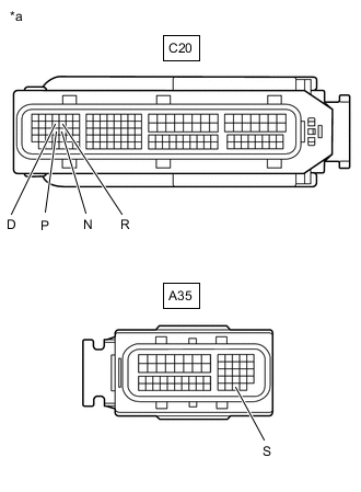
*a Front view of wire harness connector
(to ECM)
Measure the voltage according to the value(s) in the table below.
Standard Voltage Tester Connection Shift Lever Position Switch Condition Specified Condition C20-64 (P) - Body ground P Engine switch on (IG) 11 to 14 V Except P Engine switch on (IG) Below 1 V C20-35 (R) - Body ground R Engine switch on (IG) 11 to 14 V Except R Engine switch on (IG) Below 1 V C20-65 (N) - Body ground N Engine switch on (IG) 11 to 14 V Except N Engine switch on (IG) Below 1 V C20-34 (D) - Body ground D, M, "+" or "-" Engine switch on (IG) 11 to 14 V Except D, M, "+" and "-" Engine switch on (IG) Below 1 V A35-59 (S) - Body ground M, "+" or "-" Engine switch on (IG) 11 to 14 V Except M, "+" and "-" Engine switch on (IG) Below 1 V Result Proceed to OK NG
OK
REPLACE ECM Click here
NG
REPAIR OR REPLACE HARNESS OR CONNECTOR
-
-
CHECK HARNESS AND CONNECTOR (PARK/NEUTRAL POSITION SWITCH ASSEMBLY - ECM)
-
Disconnect the ECM connector.
-
Measure the resistance according to the value(s) in the table below.
Standard Resistance Tester Connection Condition Specified Condition C14-4 (B) - A35-57 (NSW) Always Below 1 Ω C14-4 (B) or A35-57 (NSW) - Body ground and other terminals Always 10 kΩ or higher Result Proceed to OK NG
OK
REPLACE ECM Click here
NG
REPAIR OR REPLACE HARNESS OR CONNECTOR
-