DOOR CONTROL RECEIVER INSTALLATION
CAUTION / NOTICE / HINT
PROCEDURE
INSTALL DOOR CONTROL AND TIRE PRESSURE MONITORING SYSTEM RECEIVER ASSEMBLY (w/ Tire Pressure Warning System)
-
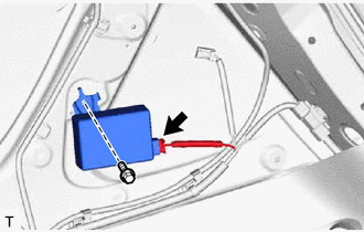
Install the door control and tire pressure monitoring system receiver assembly with the bolt.
10 N*m
102 kgf*cm
7 ft.*lbf
Connect the connector.
-
INSTALL DOOR CONTROL RECEIVER (w/o Tire Pressure Warning System)
-
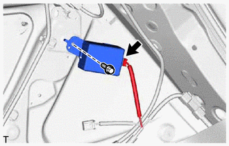
Install the door control receiver with the bolt.
10 N*m
102 kgf*cm
7 ft.*lbf
Connect the connector.
-
INSTALL INNER ROOF SIDE GARNISH ASSEMBLY RH
INSTALL SEAT BELT ANCHOR COVER CAP
INSTALL DECK TRIM SIDE PANEL ASSEMBLY RH
INSTALL DECK TRIM SERVICE HOLE COVER
INSTALL REAR DOOR OPENING TRIM WEATHERSTRIP RH
INSTALL REAR DOOR SCUFF PLATE RH
INSTALL REAR SEAT ASSEMBLY
INSTALL REAR NO. 1 FLOOR MAT SUPPORT SIDE PLATE
INSTALL REAR DECK TRIM COVER (for Full Size Spare Tire)
INSTALL REAR FLOOR FINISH PLATE (w/o Spare Tire, for Compact Spare Tire)
INSTALL REAR NO. 2 FLOOR BOARD
INSTALL DECK BOARD ASSEMBLY
INSTALL TONNEAU COVER ASSEMBLY (w/ Tonneau Cover)
INSTALL PACKAGE TRAY TRIM POCKET SUB-ASSEMBLY (w/ Partition Net)