MANIFOLD ABSOLUTE PRESSURE SENSOR ON-VEHICLE INSPECTION
PROCEDURE
INSPECT DIESEL TURBO PRESSURE SENSOR
-
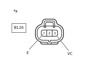
*a
Front view of wire harness connector
(to Diesel Turbo Pressure Sensor)
Inspect the power source voltage.
Disconnect the connector from the diesel turbo pressure sensor.
Turn the ignition switch to ON.
Measure the voltage according to the value(s) in the table below.
Standard Voltage
Tester Connection
Condition
Specified Condition
B126 - 3 (VC) - B126 - 1 (E)
Ignition switch ON
4.75 to 5.25 V
Turn the ignition switch off.
Reconnect the diesel turbo pressure sensor connector.
Clear the DTCs.
Inspect diesel turbo pressure sensor.
Connect the GTS to the DLC3.
Turn the ignition switch to ON.
Turn the GTS on.
Enter the following menus: Powertrain / Engine and ECT / Data List / Map and Atmosphere Pressure.
Powertrain > Engine and ECT > Data List
Tester Display
Atmosphere Pressure
MAP
Disconnect the vacuum hose from the diesel turbo pressure sensor.
-
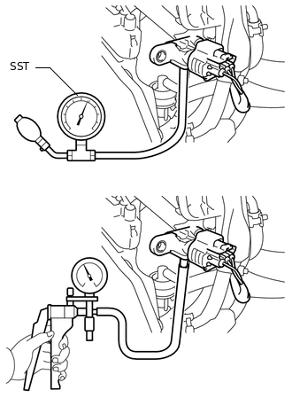
Using SST, apply pressure to the diesel turbo pressure sensor.
09992-00242
Using a vacuum pump, apply vacuum to the diesel turbo pressure sensor.
Read the value.
OK
Condition
Map Value
No pressure applied
Same as atmospheric pressure
Vacuum applied
Indicates vacuum
Pressure applied
Indicates pressure
If the result is not as specified, replace the manifold absolute diesel turbo pressure sensor or ECM.
-