IMMOBILISER SYSTEM(w/o Entry and Start System), Diagnostic DTC:B279A
| DTC Code | DTC Name |
|---|---|
| B279A | Theft Deterrent System Communication Line High Fixation |
DESCRIPTION
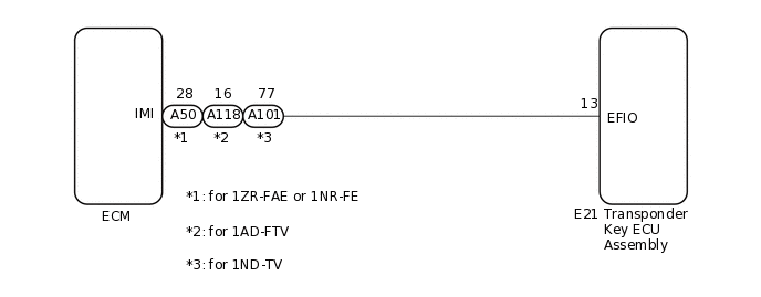
If the communication line (EFIO-IMI) to the transponder key ECU assembly is stuck high (e.g. shorted to +B), the ECM stores this DTC.
DTC No. |
Detection Item |
DTC Detection Condition |
Trouble Area |
Note |
|---|---|---|---|---|
B279A |
Theft Deterrent System Communication Line High Fixation |
Communication line (EFIO-IMI) between the ECM and transponder key ECU assembly is stuck high. |
|
|
Vehicle Condition when Malfunction Detected |
Fail-safe Operation when Malfunction Detected |
|---|---|
Engine cannot be started (initial ignition occurs and engine cranks, then ignition stops) |
Engine cannot be started |
DTC No. |
Data List and Active Test |
|---|---|
B279A |
- |
WIRING DIAGRAM
CAUTION / NOTICE / HINT
If the transponder key ECU assembly or ECM is replaced, refer to Service Bulletin.
After repair, confirm that no DTCs are output by performing "DTC Output Confirmation Operation".
PROCEDURE
CLEAR DTC
Clear the DTCs.
Powertrain > Engine and ECT > Clear DTCs
Powertrain > Engine and ECT > Clear DTCs
Result
Proceed to
NEXT
CHECK FOR DTC
Check for DTCs.
Powertrain > Engine and ECT > Trouble Codes
Powertrain > Engine and ECT > Trouble Codes
Tip:Before checking for DTCs, perform the "DTC Output Confirmation Operation" procedure.
OK
DTC B279A is not output.
Result
Result
Proceed to
B279A is not output
A
B279A is output
B
CHECK CONNECTION OF CONNECTOR
Check that the connectors are properly connected to the ECM and transponder key ECU assembly.
OK
Connectors are properly connected.
Result
Proceed to
OK
NG
NG CONNECT CONNECTORS PROPERLY
CHECK HARNESS AND CONNECTOR (TRANSPONDER KEY ECU ASSEMBLY - ECM AND BODY GROUND)
for 1ZR-FAE or 1NR-FE
Disconnect the E21 transponder key ECU assembly connector.
Disconnect the A50 ECM connector.
Measure the resistance according to the value(s) in the table below.
Standard Resistance
Tester Connection
Condition
Specified Condition
E21-13 (EFIO) - A50-28 (IMI)
Always
Below 1 Ω
E21-13 (EFIO) - Body ground
Always
10 kΩ or higher
A50-28 (IMI) - Body ground
Always
10 kΩ or higher
for 1ND-TV
Disconnect the E21 transponder key ECU assembly connector.
Disconnect the A101 ECM connector.
Measure the resistance according to the value(s) in the table below.
Standard Resistance
Tester Connection
Condition
Specified Condition
E21-13 (EFIO) - A101-77 (IMI)
Always
Below 1 Ω
E21-13 (EFIO) - Body ground
Always
10 kΩ or higher
A101-77 (IMI) - Body ground
Always
10 kΩ or higher
for 1AD-FTV
Disconnect the E21 transponder key ECU assembly connector.
Disconnect the A118 ECM connector.
Measure the resistance according to the value(s) in the table below.
Standard Resistance
Tester Connection
Condition
Specified Condition
E21-13 (EFIO) - A118-16 (IMI)
Always
Below 1 Ω
E21-13 (EFIO) - Body ground
Always
10 kΩ or higher
A118-16 (IMI) - Body ground
Always
10 kΩ or higher
Result
Proceed to
OK
NG
NG REPAIR OR REPLACE HARNESS OR CONNECTOR
REPLACE TRANSPONDER KEY ECU ASSEMBLY
Replace the transponder key ECU assembly with a new one.
Result
Proceed to
NEXT
CLEAR DTC
Clear the DTCs.
Powertrain > Engine and ECT > Clear DTCs
Powertrain > Engine and ECT > Clear DTCs
Result
Proceed to
NEXT
CHECK FOR DTC
Check for DTCs.
Tip:Before checking for DTCs, perform the "DTC Output Confirmation Operation" procedure.
OK
DTC B279A is not output.
Result
Result
Proceed to
B279A is not output
A
B279A is output (for 1AD-FTV)
B
B279A is output (for 1ND-TV)
C
B279A is output (for 1NR-FE)
D
B279A is output (for 1ZR-FAE)
E
A END (TRANSPONDER KEY ECU ASSEMBLY WAS DEFECTIVE)