ENTRY AND START SYSTEM(for Start Function) Power Source Mode does not Change to ON (ACC)
DESCRIPTION
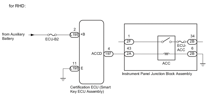
When the key is in the vehicle and the power switch is pressed, the certification ECU (smart key ECU assembly) receives a signal and changes the power source mode.
Use this troubleshooting procedure when the power source mode does not change to on (ACC) but does change to on (IG).
Tech Tips
-
When the certification ECU (smart key ECU assembly) is replaced with a new one and the cable is connected to the negative (-) auxiliary battery terminal, the power source mode changes to on (IG).
-
When the auxiliary battery cable is disconnected and reconnected, the power source returns to the mode it was in before the auxiliary battery cable was disconnected.
WIRING DIAGRAM

CAUTION / NOTICE / HINT
Note
-
Make sure that no DTCs are output. If any DTCs are output, proceed to the Diagnostic Trouble Code Chart Click here.
-
The entry and start system uses multiplex communication. First perform the inspections in "How to Proceed with Troubleshooting" to confirm that there are no communication malfunctions before proceeding with troubleshooting Click here.
-
If the entry and start system is disabled through the customize function, enable the system before performing troubleshooting Click here.
-
Inspect the fuses for circuits related to this system before performing the following inspection procedure.
-
After completing repairs, confirm that the problem does not occur.
Tech Tips
| Problem Symptom | Data List Item | Active Test Item |
|---|---|---|
| Power source mode does not change to on (ACC) but does change to on (IG) |
Power Source Control |
- |
PROCEDURE
-
CHECK HARNESS AND CONNECTOR (CERTIFICATION ECU (SMART KEY ECU ASSEMBLY) - INSTRUMENT PANEL JUNCTION BLOCK ASSEMBLY)
-
Disconnect the L197 certification ECU (smart key ECU assembly) connector.
-
Disconnect the 2A and 2B instrument panel junction block assembly connectors.
-
Measure the resistance according to the value(s) in the table below.
Standard Resistance Tester Connection Condition Specified Condition L197-4 (ACCD) - 2A-25 Always Below 1 Ω 2B-9 - Body ground Always Below 1 Ω L197-4 (ACCD) or 2A-25 - Body ground Always 10 kΩ or higher
NG 
REPAIR OR REPLACE HARNESS OR CONNECTOR
OK 
-
-
CHECK INSTRUMENT PANEL JUNCTION BLOCK ASSEMBLY
-
Remove the instrument panel junction block assembly.
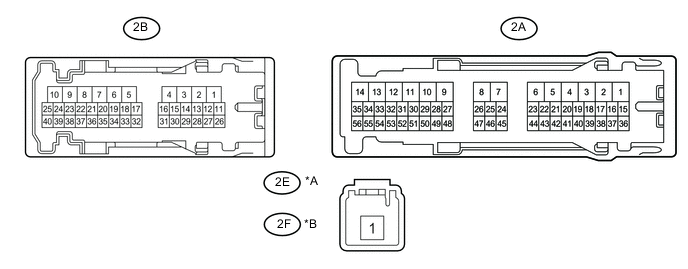
Text in Illustration *A for LHD *B for RHD *a Component without harness connected
(Instrument Panel Junction Block Assembly)
- - -
Remove the main body ECU (multiplex network body ECU) from the instrument panel junction block assembly
-
Measure the resistance according to the value(s) the table below.
Standard Resistance Tester Connection Condition Specified Condition 2E-1 - 2B-13*1
2F-1 - 2B-13*2
Auxiliary battery voltage not applied between terminals 2A-25 and 2B-9 10 kΩ or higher Auxiliary battery voltage applied between terminals 2A-25 and 2B-9 Below 1 Ω
-
*1: for LHD
-
*2: for RHD
-
NG
REPLACE INSTRUMENT PANEL JUNCTION BLOCK ASSEMBLY Click here
OK
-
-
INSPECT CERTIFICATION ECU (SMART KEY ECU ASSEMBLY)
-
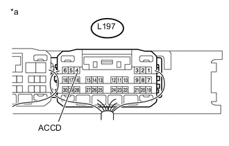
Text in Illustration *a Component with harness connected
(Certification ECU (Smart Key ECU Assembly))
Reconnect the L197 certification ECU (smart key ECU assembly) connector.
-
Measure the voltage according to the value(s) in the table below.
Standard Voltage Tester Connection Condition Specified Condition L197-4 (ACCD) - Body ground Power switch off → Power switch on (ACC)) 1 V or less → 8.5 V or higher
OK
USE SIMULATION METHOD TO CHECK Click here
NG
REPLACE CERTIFICATION ECU (SMART KEY ECU ASSEMBLY)
-