ANTI-LOCK BRAKE SYSTEM, Diagnostic DTC:C0210/33, C0215/34, C1238/38, C1239/39, C1273/73, C1274/74, C1277/77, C1278/78
| DTC Code | DTC Name |
|---|---|
| C0210/33 | Rear Speed Sensor RH Circuit |
| C0215/34 | Rear Speed Sensor LH Circuit |
| C1238/38 | Foreign Object is Attached on Tip of Rear Speed Sensor RH |
| C1239/39 | Foreign Object is Attached on Tip of Rear Speed Sensor LH |
| C1273/73 | Low Output Signal of Rear Speed Sensor RH (Test Mode DTC) |
| C1274/74 | Low Output Signal of Rear Speed Sensor LH (Test Mode DTC) |
| C1277/77 | Abnormal Change in Output Signal of Rear Speed Sensor RH (Test Mode DTC) |
| C1278/78 | Abnormal Change in Output Signal of Rear Speed Sensor LH (Test Mode DTC) |
DESCRIPTION
Refer to DTCs C0200/31, C0205/32, C1235/35, and C1236/36 Click here.
DTCs C1273/73 to C1278/78 can be cleared when the speed sensor sends a vehicle speed signal or the Test Mode ends. DTCs C1273/73 to C1278/78 are output only in the Test Mode.
Tech Tips
When the connectors between the speed sensor and skid control ECU (brake actuator assembly) are connected, the following waveform is output.
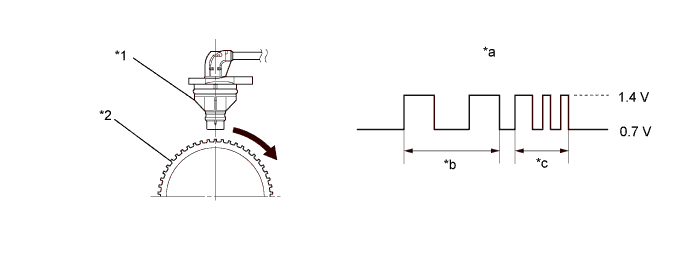
| *1 | Rear Speed Sensor | *2 | Rear Skid Control Rotor |
| *a | Waveform (Reference): Between Speed Sensor (-) and Body Ground |
*b | Low speed |
| *c | High speed | - | - |
| DTC No. | DTC Detection Condition | Trouble Area |
|---|---|---|
| C0210/33 C0215/34 |
|
|
| C1238/38 C1239/39 |
With the vehicle speed 20 km/h (12 mph) or higher, noise is detected 75 times in the speed sensor signal within 5 seconds. |
|
| C1273/73 C1274/74 |
Detected only during Test Mode. |
|
| C1277/77 C1278/78 |
Detected only during Test Mode. |
|
Tech Tips
-
DTC C0210/33 and C1238/38 are for the rear speed sensor RH.
-
DTC C0215/34 and C1239/39 are for the rear speed sensor LH.
WIRING DIAGRAM
INSPECTION PROCEDURE
PROCEDURE
-
READ VALUE USING INTELLIGENT TESTER (MOMENTARY INTERRUPTION OF REAR SPEED SENSOR)
-
Using a GTS, check for any momentary interruption in the wire harness and connector corresponding to the DTC Click here.
ABS/VSC/TRC Tester Display Measurement Item/Range Normal Condition Diagnostic Note RR Speed Open Rear speed sensor RH open detection / Error or Normal Normal Error: Momentary interruption RL Speed Open Rear speed sensor LH open detection / Error or Normal Normal Error: Momentary interruption OK Normal (There are no momentary interruptions.) Tech Tips
Perform the above inspection before removing the sensor and connector.
NG 
CHECK HARNESS AND CONNECTOR (BRAKE ACTUATOR ASSEMBLY - REAR SPEED SENSOR) Click here
OK 
-
-
READ VALUE USING INTELLIGENT TESTER (REAR SPEED SENSOR)
-
Select the DATA LIST mode on the GTS.
ABS/VSC/TRC Tester Display Measurement Item/Range Normal Condition Diagnostic Note RR Wheel Speed Rear wheel speed sensor RH reading / min.: 0 km/h (0 mph), Max.: 326 km/h (202 mph) Vehicle stopped: 0 km/h (0 mph) When driving at constant speed: No large fluctuations RL Wheel Speed Rear wheel speed sensor LH reading / min.: 0 km/h (0 mph), Max.: 326 km/h (202 mph) Vehicle stopped: 0 km/h (0 mph) When driving at constant speed: No large fluctuations -
Check that the speed value output from the speed sensor displayed on the GTS and the speed value displayed on the speedometer are almost the same when driving the vehicle.
OK The speed value output from the speed sensor displayed on the GTS is the same as the actual vehicle speed.
NG
INSPECT REAR SPEED SENSOR INSTALLATION Click here
OK
-
-
PERFORM TEST MODE (SIGNAL CHECK)
-
Perform sensor signal check in TEST MODE PROCEDURE Click here.
OK All Test Mode DTCs are cleared.
NG
INSPECT REAR SPEED SENSOR INSTALLATION Click here
OK
-
-
RECONFIRM DTC
-
Clear the DTCs Click here.
-
Drive the vehicle at a speed of approximately 30 km/h (19 mph) or more for 60 seconds or more.
-
Check that the same DTCs are recorded Click here.
Result Result Proceed to DTC is not output A DTC is output B Tech Tips
If troubleshooting has been carried out according to the Problem Symptoms Table, refer back to the table and proceed to the next step Click here.
B
REPLACE REAR SPEED SENSOR Click here
A 
USE SIMULATION METHOD TO CHECK Click here
-
-
INSPECT REAR SPEED SENSOR INSTALLATION
-
Turn the ignition switch off.
-
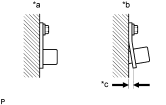
Text in Illustration *a Normal *b Abnormal *c Clearance Check the speed sensor installation Click here.
OK There is no clearance between the sensor and the rear axle housing. The installation nut is tightened properly. Note
Check the speed sensor signal after replacement Click here.
NG 
INSTALL REAR SPEED SENSOR CORRECTLY OR REPLACE REAR SPEED SENSOR
OK
-
-
INSPECT SPEED SENSOR TIP
-
Remove the rear speed sensor Click here.
-
Check the sensor tip.
OK No scratches or foreign matter on the sensor tip. Note
-
If no damage to the speed sensor tip is found during this inspection, do not replace the speed sensor.
-
If there is iron powder sticking to the rotor, this will result in a malfunction, so confirm that the rotor is not contaminated with foreign material before replacing the sensor.
-
Check the speed sensor signal after cleaning or replacement Click here.
-
NG
CLEAN OR REPLACE REAR SPEED SENSOR
OK
-
-
INSPECT REAR SKID CONTROL ROTOR
-
Remove the rear axle shaft with backing plate Click here.
-
Check the rear skid control rotor.
OK No scratches, oil, or foreign matter on the rotors. Note
Check the speed sensor signal after cleaning or replacement Click here.
-
Reinstall the rear speed sensor and the rear axle shaft with backing plate Click here for speed sensor, Click here for rear axle shaft with backing plate).
NG
CLEAN OR REPLACE REAR SKID CONTROL ROTOR
OK
-
-
CHECK HARNESS AND CONNECTOR (BRAKE ACTUATOR ASSEMBLY - REAR SPEED SENSOR)
-
Turn the ignition switch off.
-
Make sure that there is no looseness at the locking part and the connecting part of the connectors.
-
Disconnect the B19 skid control ECU (brake actuator assembly) connector and the P1 rear speed sensor connector.
-
Measure the resistance according to the value(s) in the table below.
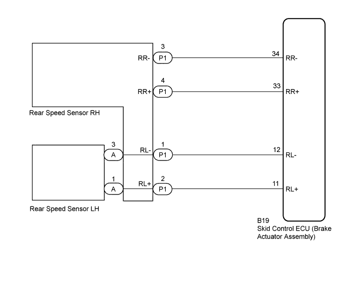
Standard Resistance for RH Tester Connection Condition Specified Condition B19-33 (RR+) - P1-4 (RR+) Always Below 1 Ω B19-33 (RR+) or P1-4 (RR+) - Body ground Always 10 kΩ or higher B19-34 (RR-) - P1-3 (RR-) Always Below 1 Ω B19-34 (RR-) or P1-3 (RR-) - Body ground Always 10 kΩ or higher for LH Tester Connection Condition Specified Condition B19-11 (RL+) - P1-2 (RL+) Always Below 1 Ω B19-11 (RL+) or P1-2 (RL+) - Body ground Always 10 kΩ or higher B19-12 (RL-) - P1-1 (RL-) Always Below 1 Ω B19-12 (RL-) or P1-1 (RL-) - Body ground Always 10 kΩ or higher
NG
REPAIR OR REPLACE HARNESS OR CONNECTOR
OK
-
-
INSPECT REAR SPEED SENSOR RH
-
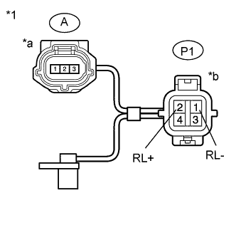
Text in Illustration *1 Rear Speed Sensor RH *a Front view of wire harness connector
(to Sensor Side Connector)
*b Front view of wire harness connector
(to Vehicle Side Connector)
Turn the ignition switch off.
-
Make sure that there is no looseness at the locking part and the connecting part of the connectors.
-
Disconnect the A rear speed sensor RH connector.
-
Measure the resistance according to the value(s) in the table below.
Standard Resistance Tester Connection Condition Specified Condition A-3 - P1-1 (RL-) Always Below 1 Ω A-3 or P1-1 (RL-) - Body ground Always 10 kΩ or higher A-1 - P1-2 (RL+) Always Below 1 Ω A-1 or P1-2 (RL+) - Body ground Always 10 kΩ or higher Note
Check the speed sensor signal after replacement Click here.
NG
REPLACE REAR SPEED SENSOR RH Click here
OK
-
-
INSPECT BRAKE ACTUATOR ASSEMBLY
-
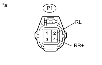
Text in Illustration *a Front view of wire harness connector
(to Rear Speed Sensor RH)
Reconnect the B19 skid control ECU (brake actuator assembly) connector.
-
Turn the ignition switch to ON.
-
Measure the voltage according to the value(s) in the table below.
Standard Voltage for RH Tester Connection Switch Condition Specified Condition P1-4 (RR+) - Body ground Ignition switch ON 5.7 to 14 V for LH Tester Connection Switch Condition Specified Condition P1-2 (RL+) - Body ground Ignition switch ON 5.7 to 14 V Note
Check the speed sensor signal after replacement Click here.
NG
REPLACE BRAKE ACTUATOR ASSEMBLY Click here
OK
-
-
RECONFIRM DTC
-
Reconnect the A and P1 rear speed sensor RH connectors.
-
Clear the DTCs Click here.
-
Drive the vehicle at a speed of approximately 30 km/h (19 mph) or more for 60 seconds or more.
-
Check that the same DTCs are recorded Click here.
Result Result Proceed to DTC is not output A DTC is output B
B
REPLACE REAR SPEED SENSOR Click here
A
USE SIMULATION METHOD TO CHECK Click here
-
-
REPLACE REAR SPEED SENSOR
-
Replace the rear speed sensor Click here.
Note
Check the speed sensor signal after replacement Click here.
NEXT
-
-
RECONFIRM DTC
-
Clear the DTCs Click here.
-
Drive the vehicle at a speed of approximately 30 km/h (19 mph) or more for 60 seconds or more.
-
Check that the same DTCs are recorded Click here.
Result Result Proceed to DTC is not output A DTC is output B
B
REPLACE REAR SKID CONTROL ROTOR Click here
A
END
-
-
REPLACE REAR SKID CONTROL ROTOR
-
Replace the rear skid control rotor Click here.
Note
Check the speed sensor signal after replacement Click here.
NEXT
-
-
RECONFIRM DTC
-
Clear the DTCs Click here.
-
Drive the vehicle at a speed of approximately 30 km/h (19 mph) or more for 60 seconds or more.
-
Check that the same DTCs are recorded Click here.
Result Result Proceed to DTC is not output A DTC is output B
B
REPLACE BRAKE ACTUATOR ASSEMBLY Click here
A
END
-