PANORAMIC VIEW MONITOR SYSTEM
-
OUTLINE
-
A panoramic view monitor system is provided which displays a panoramic view of the vehicle to assist the driver during parking and low speed driving. The panoramic image is created by seamlessly combining images from each television camera assembly installed to the front, rear, left and right sides of the vehicle.
-
The panoramic view monitor system provides a variety of image display modes to make confirming the area around the vehicle possible according to driving conditions. These display modes include the simultaneous display of the panoramic view and the front view or rear view, or the simultaneous display of the left and right sides of the vehicle.
-
This system uses the full-screen display on the 10.3-inch wide display to make it possible for the driver to easily confirm the surroundings and simultaneously confirm a wide range on a single screen.
-
The "side view and wide front view", "side view and rear view" and "side view and wide rear view" screens are provided. Even with the outer rear view mirrors retracted, the system helps the driver confirm the safety of the surroundings and park close to objects, etc.
-
Images from the front television camera assembly and the left and right side television camera assemblies are combined and a "panoramic view and side clearance view" looking down on the front side of the vehicle from behind are used, allowing the driver to intuitively confirm the space on the sides of the vehicle when passing another vehicle on a narrow road or when driving close to the sides of the road.
-
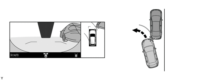
Images from a perspective diagonal from the rear of the vehicle are displayed to make it easier to confirm the rear inner wheel and surrounding area during turning. A "panoramic view and cornering view" is used to confirm catching due to inner wheel difference, confirm safety when turning right or left on narrow roads and help prevent hitting the curb when pulling onto a roadway.
-
A function, which automatically displays the panoramic view and wide front view screen when the Lexus parking assist-sensor system detects an obstacle at low speeds, is used. In addition, a panoramic view zoom function, which enlarges images from the left and right corners of the vehicle in the traveling direction (forward or backward), is provided.
Note
Do not rely solely upon the panoramic view monitor system. As with unequipped models, drive carefully while directly confirming the safety of your surroundings.
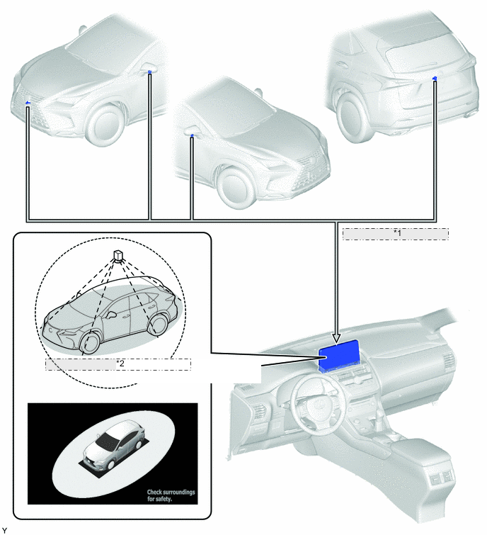
*1 Combines Video Signals from Each Television Camera Assembly *2 Displays Overhead View of Vehicle Display Mode Display Shift Position Notes See Through View Mode 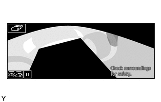
P Used to check the conditions around the vehicle from a first-person perspective when the vehicle is parked. Moving View Mode 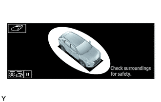
P Used to check the conditions around the vehicle from a third-person perspective when the vehicle is parked. Panoramic View and Wide Front View Mode 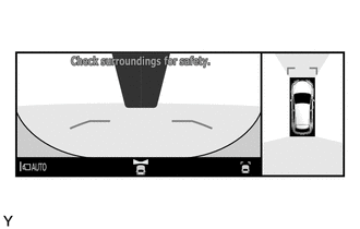
D, M or N Used to check the conditions around and in front of the vehicle when driving at low speed. Panoramic View and Side Clearance View Mode 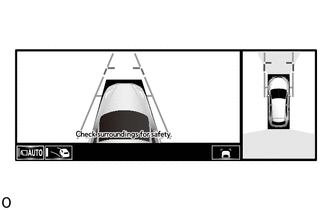
D, M or N Used to check the conditions around and in front of the vehicle when driving at low speed. Panoramic View and Cornering View Mode 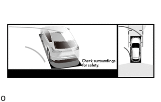
D, M or N Used to check the area around the vehicle and the sides of the vehicle at low speed. Panoramic View and Rear View Mode 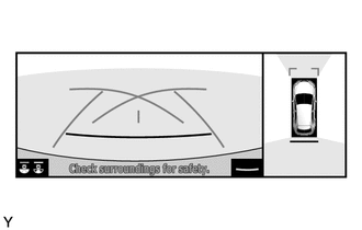
R When backing up, this is used to check the conditions around and behind the vehicle. Panoramic View and Wide Rear View Mode 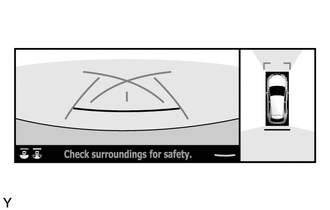
R When backing up, this is used to check the conditions around and behind the vehicle. Side View and Wide Front View Mode 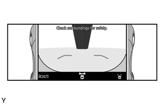
D, M or N When the outer rear view mirrors are retracted, this is used to check the conditions around the dual side and in front of the vehicle. Side View and Rear View Mode 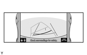
R When the outer rear view mirrors are retracted, this is used to check the conditions around the dual side and behind the vehicle. Side View and Wide Rear View Mode 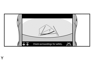
R When the outer rear view mirrors are retracted, this is used to check the conditions around the dual side and behind the vehicle. Tech Tips
The illustrations shown are example only. The illustrations may differ from the actual vehicle screens.
-
-
MAIN FEATURES
-
The panoramic view monitor system seamlessly combines images from the front, rear, left and right television camera assemblies and displays the combined images as the panoramic view image. Also, the system assists the driver to confirm the area around the vehicle while driving at low speeds and driving during parking by simultaneously displaying the panoramic view and front (wide front view), rear (rear view and wide rear view) images, an overhead view of the front of the vehicle from the rear (side clearance view) or an overhead view of the vehicle diagonally from the rear (cornering view), etc., on the multi-display assembly.
-
The front image (wide front view) helps the driver confirm whether it is safe to start off at locations with poor visibility, such as intersections and T-junctions.
-
The rear image (rear view and side rear view screen) helps the driver reverse the vehicle.
-
The overhead view of the front of the vehicle from the rear (side clearance view) helps the driver to confirm the safety of the areas to the sides of the vehicle, avoid contact with obstacles on narrow roads and drive close to the shoulder.
-
The overhead view of the vehicle diagonally from the rear (cornering view) helps the driver to confirm safety when turning right or left on narrow roads and prevent hitting the curb when pulling onto a roadway.
Note
The panoramic view monitor system is an auxiliary device used to confirm the area around the vehicle. Always drive while directly confirming the surroundings of the vehicle (particularly the area to the rear).
-
-
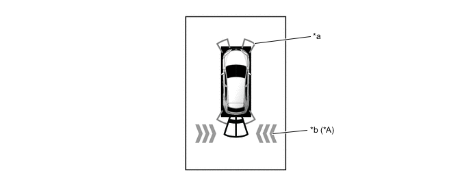
The see through view and moving view combines images from the cameras on the front, rear, and both sides of the vehicle into a simulated video display of the area surrounding the vehicle. By reducing the size of the blind spots from inside the vehicle, it assists in confirming the safety of the area around the vehicle.
Tech Tips
The see through view and moving view screens can be displayed when the Lexus parking assist-sensor system is on.
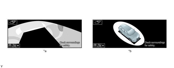
*a See Through View *b Moving View
-
-
PRECAUTION
-
When driving, directly confirm the surroundings of the vehicle (particularly the area to the rear). Failure to do so can lead to unforeseen accidents, such as collisions with other vehicles, etc. Make sure to observe the following precautions when using the panoramic view monitor system.
-
Do not rely solely upon the panoramic view monitor system. As with unequipped models, drive carefully while directly confirming the safety of your surroundings.
-
When driving, directly confirm the safety of your surroundings. Do not drive while only viewing the monitor screen.
-
When driving using the system, drive carefully while depressing the brake pedal to adjust the vehicle speed.
-
Do not use the panoramic view monitor system under the following situations.
-
The road surface is slippery (frozen or covered with snow).
-
Snow chains or spare tires are used.
-
The vehicle is driven on the road that is not even, such as a slope.
-
The front doors and the back door are not fully closed.
-
Tires have been replaced with non-genuine tires.
-
The suspension has been modified.
-
-
When the outside air temperature is low, the screen may become darker or appear faint. Since moving objects in particular may become distorted or disappear, always drive carefully while directly confirming the safety of your surroundings.
-
When tires are replaced, the position indicated by the guide lines displayed on the monitor may differ slightly.
-
The position of the guide lines displayed on the monitor may differ depending on the number of passengers, load capacity, road grade, etc. Always drive while directly confirming the surroundings of the vehicle (particularly the area to the rear).
-
-
Precautions for Panoramic View Monitor System Screen Display
-
The see through view, moving view, side clearance view, cornering view and panoramic view are an image created by combining images from the front, rear, left and right side television camera assemblies. Since the possible display area and display contents are limited, use the panoramic view monitor system with a full understanding of the limitations.
-
Since the 4 corners of the see through view, moving view, side clearance view, cornering view and panoramic view screens are where the images from each camera are combined, the color definition may be reduced, but this is not a malfunction.
-
The see through view, moving view, side clearance view, cornering view and panoramic view screens may appear lighter or darker according to the lighting intensity near each television camera assembly.
-
The see through view, moving view, side clearance view, cornering view and panoramic view screens do not display anything above each television camera assembly installation position and imaging range.
-
There are blind spots near the vehicle that cannot be displayed on the panoramic view monitor system.
-
Solid objects displayed on the wide front view, rear view and wide rear view screens may not be displayed on the see through view, moving view, side clearance view, cornering view and panoramic view screens.
-
The panoramic view monitor system may display solid objects such as people and obstacles in a way that may differ from actual conditions. (For example, there are cases when objects appear to be laying down, objects disappears near the areas where images are combined and vice versa, when the distance between the vehicle and an object differs from the actual distance, etc.)
-
The panoramic view monitor system does not display correctly when any of the back door, left front door and right front door is open.
-
Since the vehicle icon displayed on the see through view, moving view, side clearance view, cornering view and panoramic view screens is displayed using computer graphics, the vehicle color, shape and size may differ from the actual vehicle. Therefore, there may be cases where objects near the vehicle appear to be approaching and the distance on the display between the object and vehicle differs from the actual distance.
-
-
Area Displayed on Screen
-
See Through View, Moving View, Side Clearance View, Cornering View and Panoramic View
-
There are blind spots near the vehicle that cannot be displayed on the monitor. Even if no obstacles are displayed on the monitor, obstacles may be on the driving path and the vehicle may contact them. Always drive while directly confirming the safety of your surroundings.
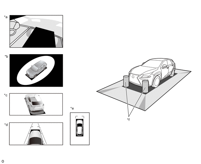
*a See Through View *b Moving View *c Cornering View *d Side Clearance View *e Panoramic View *f Obstacles in Blind Spot Area 
Blind Spot Area not Displayed on Monitor - - -
Since images captured from the 4 television camera assemblies are edited and displayed on the see through view, moving view, side clearance view, cornering view and panoramic view screens based on flat roads, the images may be displayed as follows.
-
Solid objects appear to be laying down, longer and thinner, or larger.
-
Solid objects higher than the road surface appear farther than they actually are or are not displayed at all.
-
Tall objects appear from the seams of combined images.
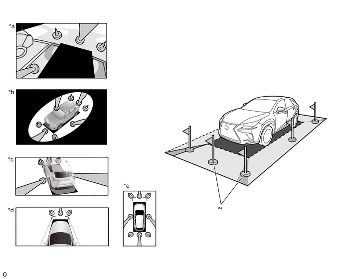
*a See Through View *b Moving View *c Cornering View *d Side Clearance View *e Panoramic View *f Obstacle -
-
The brightness of each television camera image may appear lighter or darker according to the lighting intensity.
-
Changes in the vehicle tilt or height due to the number of occupants, the loading of the vehicle and the fuel level may cause the displayed image to be displayed.
-
Display images and guide lines may not be displayed correctly when any door equipped with a camera is not fully closed.
-
The distance between the vehicle icon and the road condition/obstacle displayed on the see through view, moving view, side clearance view, cornering view and panoramic view screens may differ from the actual distance.
-
The image definition may be low in the areas where the images are combined.
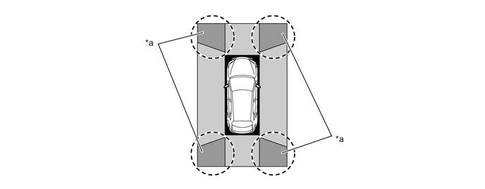
*a Image Combination Area - -
-
-
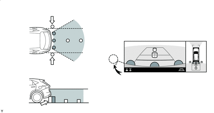
Wide Front View, Rear View and Wide Rear View
-
The display area may differ depending on the vehicle and road conditions.
-
Since the display range of the television camera assembly is limited, objects near the bottom of the bumper cannot be displayed.
-
The distance displayed on the monitor differs from the actual distance.
-
Since each television camera assembly uses a special lens, the distance displayed on the monitor differs from the actual distance.
-
Objects positioned higher than the television camera assembly may not be displayed on the monitor.
Figure 1. Front Television Camera Assembly Visible Area (Wide Front View Screen)

Obstacle Not Displayed - - Figure 2. Rear Television Camera Assembly Visible Area (Rear View Screen)
Obstacle Not Displayed - - Figure 3. Rear Television Camera Assembly Visible Area (Wide Rear View Screen)
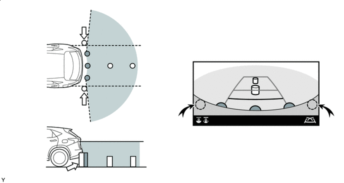
Obstacle Not Displayed - - -
-
-
Television Camera Assembly Precautions
-
Make sure to follow the precautions below to ensure the panoramic view monitor system operates normally.
-
Do not subject the camera to strong impacts by hitting it, throwing objects at it, etc. The installation position and angle of the camera may become misaligned.
-
The camera has a waterproof structure. Do not remove, disassemble or modify the camera.
-
When cleaning the camera lens, wash the camera with a large amount of water and wipe the lens with a wet soft cloth. Do not strongly rub the camera lens. Otherwise, the lens may get damaged and the camera may not be able to capture clear images.
-
The cover of the camera is made of resin. Do not apply organic solvents, wax, oil film remover, glass coating, etc. If the camera is contaminated, immediately wipe it off.
-
Do not subject the camera to sudden temperature changes such as by pouring hot water into the camera under cold weather.
-
When washing the vehicle with a high-pressure washer, do not spray water on the rear television camera assembly or surrounding area. High-pressure water can damage the camera.
-
-
If the camera is hit, a malfunction may occur. Have the vehicle inspected by your dealer as soon as possible.
-
-
Road Condition Precautions
-
Combined images and guide lines on the panoramic view monitor system show the distance based on a flat road surface. Therefore, in the following conditions, the distance and traveling path indicated by the guide lines displayed on the monitor may slightly differ from the actual ones.
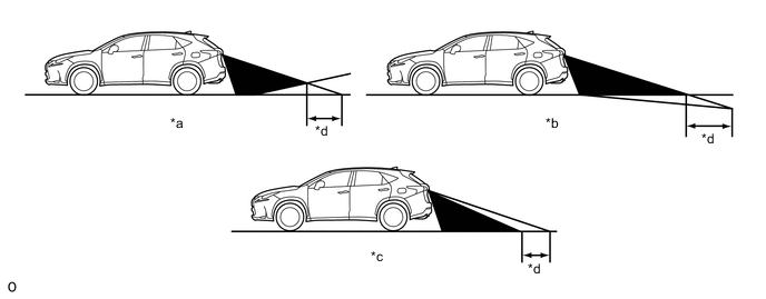
*a Steep Uphill Incline behind Vehicle *b Steep Downhill Incline behind Vehicle *c Vehicle Posture Changed by Passengers and Load *d Disparity -
If a steep uphill incline is behind the vehicle, an obstacle will appear to be further away than it actually is, as shown in the illustration below.
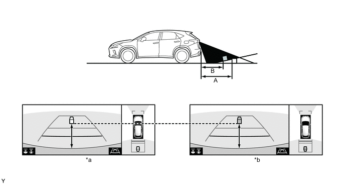
*a Screen Image in Case A *b Screen Image in Case B
-
-
Precautions for 3-Dimensional Obstacles
-
Guide lines on the monitor are for flat surfaces (such as roads, etc.). When protruding solid objects (obstacles such as a truck rear deck) or solid objects located higher than the road surface (the bumper, etc.) are nearby, directly confirm the surroundings of the vehicle.
-
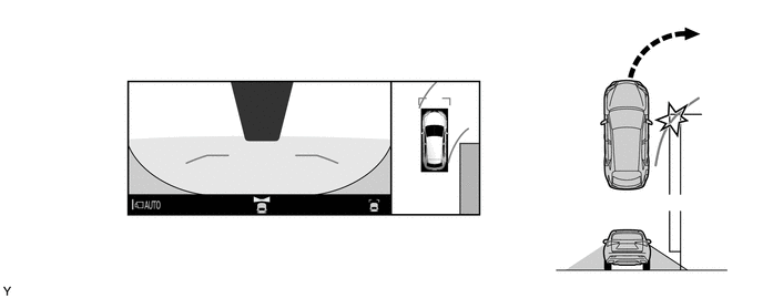
Since the estimated course lines of the panoramic view screen are displayed based on a flat road surface, solid objects located higher than the road surface (such as the bumper, protruding wall, truck rear deck, etc.) may not be displayed on the monitor or their actual locations may not be judged. Even if a solid object is outside of the estimated course lines and appears as if it will not contact the vehicle, the object may actually be on the path and the vehicle may contact the object.
-
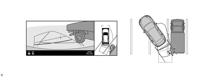
Since the estimated course lines of the rear view and wide rear view screens are displayed based on flat roads, the location of solid objects cannot be judged. Even if a truck rear deck is outside of the estimated course lines and appears as if it will not contact the vehicle, the rear deck may actually be protruding into the path and the vehicle may contact the rear deck.
-
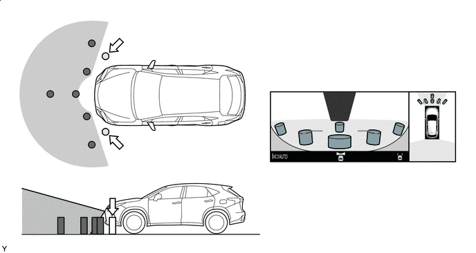
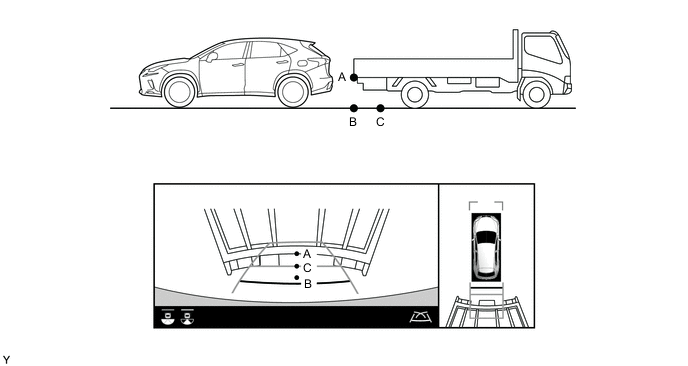
The distance indication as shown on the screen varies between 3-dimensional objects such as a vehicle and objects on a flat plane such as the road surface. As shown in the following illustration, points A and B are actually vertically aligned and point C is farther away from them. However, the points are displayed in order of distance from the vehicle, B, C and A. Therefore, the vehicle will come into contact with the 3-dimensional object if it is backed up to point B on the screen.
-
-
Icon Display
-
The icons of the Lexus parking assist-sensor system and RCTA function are displayed superimposed on a view captured by the camera. The icons may difficult to see depending on the brightness and color of the surroundings.
*a Lexus Parking Assist-sensor System Icon *b RCTA Icon
-
-