ENGINE UNIT
-
CONSTRUCTION
-
The cylinder head structure has been simplified by separating the camshaft housing (cam journal portion) from the cylinder head.
-
A long-nozzle type fuel injector assembly for port injection, which has a protruding design, is used to optimize the intake airflow. Also, the fuel injection angle and port shape are optimized in consideration of reducing fuel adhesion to achieve low fuel consumption and low emissions.
-
An aluminum alloy with superior heat conductance is used for the cylinder head sub-assembly. Weight reduction is achieved due to a reduction in the number and thickness of parts.
-
A valve lash adjuster assembly is positioned on the upper portion of the cylinder head, and the oil supply passage that runs to the valve lash adjuster assembly is installed in the cylinder head sub-assembly.
-
The shapes of the intake air port, injector fuel injection and combustion chamber are optimized to improve fuel economy via high-speed combustion and expand the driving range at the stoichiometric air-fuel ratio by improving combustion.
-
The entire cylinder head has been made thinner to achieve weight reduction.
-
The exhaust manifold is built into the cylinder head to achieve size and weight reduction. The turbocharger sub-assembly uses a twin-scroll structure, which positions the No. 1 and No. 4 cylinder exhaust port and No. 2 and No. 3 cylinder exhaust port close together inside the cylinder head. Turbo pressure response performance is improved by positioning the exhaust ports closely without interference from exhaust gas pressure.
-
The shape of the water jacket is optimized to reduce the temperature of combustion chamber components and minimize the temperature difference between cylinders. These two improvements achieve a high compression ratio, which achieves high torque, high engine output and low fuel consumption.
-
The water jacket inside the cylinder head uses a 2-stage construction. Coolant is concentrated in the bottom of the water jacket to improve the cooling of the combustion chamber. Also, the wall between the upper and lower water jackets is reinforced to support the high pressure and heat load increase due to supercharging.
-
In order to reduce the temperature of the exhaust gas that flows into the turbocharger sub-assembly to ensure the reliability of the intake system and expand the driving range limited by the stoichiometric air-fuel ratio, the exhaust manifold integrated into the cylinder head is cooled by the water jacket inside the cylinder head, cooling the exhaust gas.
-
A sub-water jacket is used around the exhaust ports to improve the following:
-
Heater performance due to warm-up improvements
-
Fuel economy due to reduced friction
-
Reliability
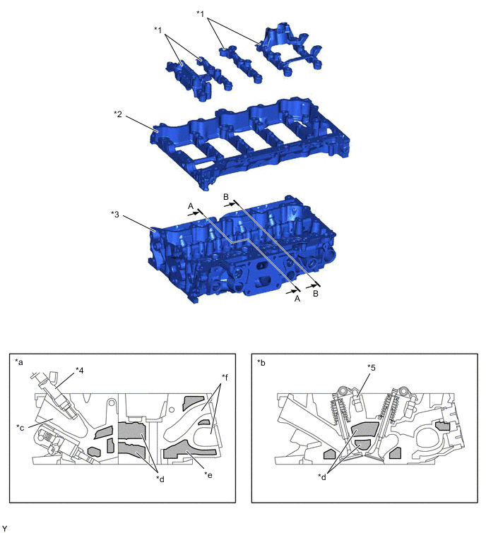
*1 Camshaft Bearing Cap *2 Camshaft Housing Sub-assembly *3 Cylinder Head Sub-assembly *4 Fuel Injector Assembly for Port Injection *5 Valve Lash Adjuster Assembly - - *a A - A Cross Section *b B - B Cross Section *c Intake Port *d Water Jacket (2-stage Construction) *e Sub-water Jacket *f Exhaust Port 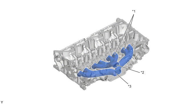
*1 Exhaust Manifold Built into Cylinder Head (Exhaust Ports) *2 Exhaust Port for No. 2 and No. 3 Cylinders *3 Exhaust Port for No. 1 and No. 4 Cylinders - -
-
-