STOP AND START
-
FUNCTION OF MAIN COMPONENTS
-
The main components in the stop and start system have the following functions:
Component Function Engine Stop and Start ECU Sends either an engine stop or restart signal to the ECM according to the signals from each sensor and switch. Engine Stop and Start ECU Backup Boost Converter
-
Supplies battery voltage to help make up for the voltage drop that occurs when the engine is restarted, preventing the operation of various systems from being interrupted due to low battery voltage.
-
Supplies battery voltage to the oil pump with solenoid assembly.
Park/Neutral Position Switch Assembly*1 Detects whether the shift lever position is in park/neutral and sends a signal to the engine stop and start ECU. Clutch Start Switch Assembly*2 Detects whether the shift lever position is in park/neutral and sends a signal to the engine stop and start ECU. Clutch Switch Assembly*2 Neutral Position Switch*2 Recognizes that the clutch pedal is depressed and sends a signal to the engine stop and start ECU. Vacuum Sensor Assembly Detects the brake booster vacuum pressure and sends a signal to the engine stop and start ECU. Hood Lock Assembly Engine Hood Courtesy Switch Detects whether the hood is open or closed and sends a signal to the engine stop and start ECU. Front Door Courtesy Light Switch Assembly (Driver Side) Detects whether the driver door is open or closed and sends a signal to the engine stop and start ECU via the combination meter assembly via CAN communication. Front Seat Inner Belt Assembly (Driver Side) Front Seat Belt Buckle Switch (Driver Side) Detects whether or not the driver's seat belt has been fastened, and sends a signal to the engine stop and start ECU via the combination meter assembly via CAN communication. Combination Meter Assembly
-
Sends an ambient temperature signal and an engine restart signal to the engine stop and start ECU.
-
Sends a front door courtesy light switch assembly (driver side) signal and front seat belt buckle switch (Driver Side) signal to the engine stop and start ECU.
Combination Meter Assembly Stop and Start Indicator Light
-
Turns on when the engine is stopped due to stop and start control.
-
Blinks to inform the driver that the idling stop is canceled and the engine will restart when the driver door is opened with the shift lever in D or S during idling stop.*1
-
If the shift lever is moved out of N without the clutch pedal depressed during idling stop, the buzzer sounds and the stop and start indicator light blinks at the same time.* 2
Stop and Start Cancel Indicator Light
-
Turns on to inform the driver that the system has been disabled when stop and start system operation is prohibited by the ecorun cancel switch assembly.
-
Blinks to inform the driver that a system malfunction has occurred, or that a part needs to be replaced after its operation count exceeds the threshold.
Multi-information Display
-
Displays the amount of time idling stop was performed since the engine switch was turned on (IG) to when the engine switch was turned off and the amount of time idling stop was performed since the reset switch was last pressed.
-
Displays the settings of the stop and start system or warning information, etc.
Ecorun Cancel Switch Assembly Operation of the system can be canceled by pressing the ecorun cancel switch assembly. Pressing the switch again or turning the power source off and back on restores the operation of the system. ECM
-
Sends various information about engine conditions to the engine stop and start ECU.
-
Based on signals from the battery sensor (battery state sensor assembly), determines whether the battery installed on the vehicle is a specified or non-specified battery, and sends the determination result to the engine stop and start ECU.
Skid Control ECU
-
Sends a vehicle speed signal to the engine stop and start ECU.
-
Sends a master cylinder pressure signal to the engine stop and start ECU.
Airbag Sensor Assembly Sends airbag deployment information in the event of a collision and a deceleration signal to the engine stop and start ECU. Battery Sensor (Battery State Sensor Assembly) Detects the battery charging and discharging amount and sends a signal to the ECM. Stop Light Switch Assembly*1 Detects a brake pedal released condition and sends a signal to the engine stop and start ECU via the ECM. Accelerator Pedal Sensor Assembly*1 Detects an accelerator pedal opening angle and sends a signal to the engine stop and start ECU via the ECM. Crank Position Sensor Detects the crankshaft angle when the engine is stopped and sends this information to the ECM. Transmission Valve Body Assembly*1 Oil Pump with Solenoid Assembly Holds the ATF pressure during idle stop. ATF Temperature Sensor Detects the ATF temperature. Transmission Valve Body Assembly*1 Absorbs negative surge produced when the ElectroMagnetic Oil Pump (EMOP) is operating. Engine Coolant Temperature Sensor Sends the coolant temperature to the engine stop and start ECU via the ECM. Generator Assembly Sends the generator assembly generation condition to the engine stop and start ECU via the ECM. *1: Models with automatic transmission
*2: Models with manual transmission
-
-
-
SYSTEM CONTROL
-
Early Stage Injection Control
-
Early stage injection control shortens the time it takes the engine to restart after the stop and start system stops the engine, allowing smooth initial acceleration.
-
The ECM memorizes the crankshaft angle detected by the crank position sensor when the engine is stopped by the stop and start system.
-
The ECM helps shorten engine start-up time by beginning fuel injection at the appropriate cylinder based on the stored crankshaft angle when the engine restarts.
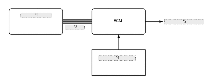
*1 Engine Stop and Start ECU *2 Fuel Injector Assembly *3 CAN (Bus 2) *4 Crank Position Sensor
-
-
Hill-start Assist Control
-
The driving force (creep phenomenon) of a former AT vehicle is regulated by depressing the brake pedal while stopped, and the driving force is transmitted by releasing the brake pedal when starting the vehicle. However, when starting a stop and start system equipped vehicle with its engine stopped due to the activation of the idling stop function, there is a short time delay before the driving force is generated as the engine will start after the brake pedal is released.
-
The hill-start assist function is a system to assist starting of a stop and start system equipped vehicle on a slope to deal with the situation described above, retaining the brake hydraulic pressure until sufficient driving force is generated.
-
-
Stop and Start System Prohibit Control
-
For safety, battery protection, comfort and ECU learning reasons, the engine stop and start ECU prohibits stop and start system operation if any one of the following conditions is met. However, there are cases which may not be applicable based on the vehicle condition or the surrounding environment.
Prohibition Reason Condition Safety If the engine is started with the engine hood open, such as when jump starting, engine restart operation cannot be ensured. Therefore, stop and start system operation will be prohibited. The operation of the system will be restored on the next trip. If the driver door or engine hood is opened before the engine stops, stop and start system operation will be prohibited for safety reasons. The brake booster vacuum is insufficient. The driver seat belt is unfastened before the engine stops. The engine catalyst is being quickly warmed up. When the drive mode is in L4 or the center differential is locked, operation of the stop and start system is prohibited.*1 Battery Protection The refresh charge continues for 0.5 to 1 hour, and is carried out approximately every 30 hours of driving. While refresh charge, stop and start system operation will be disabled. When the idling stop rate becomes higher than the predetermined rate, stop and start system operation will be disabled. When the battery voltage becomes low and the battery integrated current value drops to below the threshold value. Stop and start operation will be disabled. Comfort If the air conditioning is on when the ambient temperature is high and the evaporator temperature is high, stop and start system operation will be prohibited. If the air conditioning is on when the ambient temperature is low, stop and start system operation will be prohibited. If the heater is on when the ambient temperature is low and the engine coolant temperature is low, stop and start system operation will be prohibited. If the defroster switch and blower switch are on, stop and start system operation will be prohibited. ECU Learning ECU learning is not complete.*2 Operation If the vehicle is stopped while the steering wheel is being operated, stop and start system operation will be prohibited. Tech Tips
*1: 4WD models
*2: If the value learned by the ECU has been cleared by disconnecting the battery or for another reason, stop and start system operation will be prohibited until ECU learning is complete.
-
-
Warning Control
-
If any of the following operations are performed while the engine is stopped due to system control, the system will not restart the engine. The driver will be warned by a buzzer, the engine will be regarded as stalled, or the engine will be restarted.
Operation Warning Control Engine hood is opened. The engine status changes to stalled or is restarted. Driver's seat belt is unfastened. The engine is restarted.
-
-
Operating Conditions at Engine Stop and Restart (Models with Manual Transmission)
-
The engine may stop if all of the following conditions are detected. However, there are cases which may not be applicable based on the vehicle condition or the surrounding environment:
Item Operating Condition Idling Stop Engine Coolant Temperature 15°C to 105°C (59°F to 221°F) Driver's Door Closed Brake Booster Vacuum Sufficient brake booster vacuum Ecorun Cancel Switch Assembly Off condition Vehicle Speed The vehicle speed changes from a constant speed to 0 km/h. Engine Speed 1200 r/min or less Clutch Pedal Released Shift Lever Position Neutral*1 Driver's Seat Belt The seat belt is fastened and 3 seconds or more have elapsed. Engine Hood The engine hood is closed and 3 seconds or more have elapsed. Battery Voltage 7.6 V or more at engine start. Battery Temperature -10°C to 70°C (14°F to 158°F)*2 Battery Integrated Current*3 When the integrated current value meets any of the following conditions:
-
-5299 A-sec or more: Status of battery charge control is Charge Control Coordination Mode, Standalone Mode or Low Temperature Mode*4
-
0 A-sec or more: Status of battery charge control is Stop and Start Restriction Mode or Temperature High/Low Mode*5
Air Conditioning The cooling, heating and defrost functions are not operating. ECU Learning Completed Ambient Temperature -5°C (23°F) or more Steering Operation Not operated Highlands (low pressure) approximately 3500 m or more Tech Tips
*1: For details, see the Shift Operation and Stop and Start Control in Different Situations section.
*2: When the battery temperature becomes -15°C (5°F) or lower or 75°C (167°F) or higher, control is prohibited. After control is prohibited and the battery temperature rises to -10°C (14°F) or higher or falls to 70°C (158°F) or lower, control is performed.
*3: In the stop and start system, the engine stop and start ECU switches the system control mode (stop and start system control permitted/ prohibited) based on the battery condition (charge/discharge condition) to protect the battery and to ensure stable engine restarting performance. The battery charge-discharge condition is determined from the integrated current value calculated from the battery sensor (battery state sensor assembly)signal. The integrated current value is obtained by multiplying the current (ampere) detected by the battery sensor (battery state sensor assembly) by the time (seconds), and is expressed in the unit A-sec. This can be measured by the Global TechStream (GTS).
The engine stop and start ECU determines the power charge based on the integrated current value and prohibits stop and start system control if the value is below the threshold, because the battery might not be able to start the engine. The threshold varies according to the battery temperature and battery charge condition.
*4: After the integrated current value becomes -6451 A-sec or less, in order to charge the battery, idling stop control is prohibited until the value becomes -5299 A-sec or more.
*5: After the integrated current value becomes -1152 A-sec or less, in order to charge the battery, idling stop control is prohibited until the value becomes 0 A-sec or more.
-
-
The engine will restart if any of these conditions are detected. However, there are cases which may not be applicable based on the vehicle condition or the surrounding environment:
Item Operating Condition Engine Restart Brake Booster Vacuum The brake booster vacuum is insufficient. Air Conditioning When the air conditioning is on and a timer in the air conditioning amplifier assembly completes. When the A/C switch is on and the evaporator temperature exceeds the threshold. Either the A/C switch, blower switch, defroster switch or pollen removal mode switch is on. Ecorun Cancel Switch Assembly The ecorun cancel switch assembly is turned on. Battery
-
The battery voltage is less than 11.4 V.
-
The battery integrated current drops to below the threshold value.
Driver's Door Opened Driver's Seat Belt The driver's seat belt is unfastened. Vehicle Speed A vehicle speed signal is input. Clutch Pedal The clutch pedal is depressed. Steering Operation The steering wheel is operated. -
-
-
Operating Conditions at Engine Stop and Restart (Models with Automatic Transmission)
-
The engine may stop if all of the following conditions are detected. However, there are cases which may not be applicable based on the vehicle condition or the surrounding environment:
Item Operating Condition Idling Stop Engine Coolant Temperature 15°C to 105°C (59°F to 221°F) ATF Temperature 25°C to 112°C (77°F to 233.6°F) Driver's Door Closed Brake Booster Vacuum Sufficient brake booster vacuum Ecorun Cancel Switch Assembly Off condition Road Gradient -8° to 8° Vehicle Speed The vehicle speed changes from a constant speed to 0 km/h. Engine Speed 1200 r/min or less Shift Lever Position P, D, S*1 Driver's Seat Belt The seat belt is fastened and 3 seconds or more have elapsed. Engine Hood The engine hood is closed and 3 seconds or more have elapsed. Battery Voltage 7.6 V or more at engine start Battery Temperature -10°C to 70°C (14°F to 158°F)*2 Battery Integrated Current*3 When the integrated current value meets any of the following conditions:
-
-5299 A-sec or more: Status of battery charge control is Charge Control Coordination Mode, Standalone Mode or Low Temperature Mode*4
-
0 A-sec or more: Status of battery charge control is Stop and Start Restriction Mode or Temperature High/Low Mode*5
Air Conditioning The cooling, heating and defrost functions are not operating. ECU Learning Completed Ambient Temperature -5°C (23°F) or more Steering Operation Not operated Highlands (low pressure) approximately 3500 m or more Tech Tips
*1: For details, see the Shift Operation and Stop and Start Control in Different Situations section.
*2: When the battery temperature becomes -15°C (5°F) or lower or 75°C (167°F) or higher, control is prohibited. After control is prohibited and the battery temperature rises to -10°C (14°F) or higher or falls to 70°C (158°F) or lower, control is performed.
*3: In the stop and start system, the engine stop and start ECU switches the system control mode (stop and start system control permitted/ prohibited) based on the battery condition (charge/discharge condition) to protect the battery and to ensure stable engine restarting performance. The battery charge-discharge condition is determined from the integrated current value calculated from the battery sensor (battery state sensor assembly)signal. The integrated current value is obtained by multiplying the current (ampere) detected by the battery sensor (battery state sensor assembly) by the time (seconds), and is expressed in the unit A-sec. This can be measured by the Global TechStream (GTS).
The engine stop and start ECU determines the power charge based on the integrated current value and prohibits stop and start system control if the value is below the threshold, because the battery might not be able to start the engine. The threshold varies according to the battery temperature and battery charge condition.
*4: After the integrated current value becomes -6451 A-sec or less, in order to charge the battery, idling stop control is prohibited until the value becomes -5299 A-sec or more.
*5: After the integrated current value becomes -1152 A-sec or less, in order to charge the battery, idling stop control is prohibited until the value becomes 0 A-sec or more.
-
-
The engine will restart if any of these conditions are detected. However, there are cases which may not be applicable based on the vehicle condition or the surrounding environment:
Item Operating Condition Engine Restart Brake Booster Vacuum The brake booster vacuum is insufficient. Air Conditioning When the air conditioning is on and a timer in the air conditioning amplifier assembly completes. When the A/C switch is on and the evaporator temperature exceeds the threshold. Either the A/C switch, blower switch, defroster switch or pollen removal mode switch is on. Ecorun Cancel Switch Assembly The ecorun cancel switch assembly is turned on. Battery
-
The battery voltage is less than 11.4 V.
-
The battery integrated current drops to below the threshold value.
Driver's Door Opened Driver's Seat Belt The driver's seat belt is unfastened. Vehicle Speed A vehicle speed signal is input. Accelerator Pedal The accelerator pedal is depressed. Brake Pedal The brake pedal is released.*1 Shift Lever The shift lever is moved out of P.*2 Steering Operation The steering wheel is operated. Engine Hood The engine hood is opened.*3 Tech Tips
*1: When the shift lever is in D or S.
*2: For details, see the Shift Operation and Stop and Start Control in Different Situations section.
*3: When the shift lever is in P.
-
-
-
Multi Stop and Start Control
-
When the vehicle speed is 0 km/h during an idling stop and the engine is restarted according to the engine restart conditions, multi stop and start control stops the engine again when the engine stop and start ECU determines again that an idling stop is possible. As a result, a longer idling stop time is ensured for cases when the vehicle is stopped in one place for long periods of time, such as during traffic congestion. However, there are cases in which multi stop and start control based on engine restart conditions may not be performed.
-
Multi stop and start control operation is only possible when stop and start priority control is set to "Long".
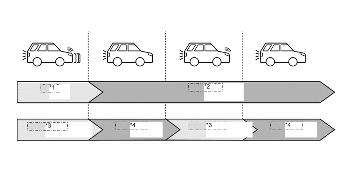
*1 Driving *2 Vehicle Stop *3 Engine Running *4 Idling Stop
-
-
Stop and Start Priority Control
-
Stop and start operation time when the air conditioning is operating can be changed between "Normal" and "Long (the stop and start system has priority)" using the steering pad switch located on the steering pad, enabling the user to select the preferred setting. However, even when selecting "Long (the stop and start system has priority)", the idling stop time may not change depending on the vehicle condition or the surrounding environment.
-
-
Shift Lever Operation and Stop and Start Control in Different Situations (Models with Automatic Transmission)
-
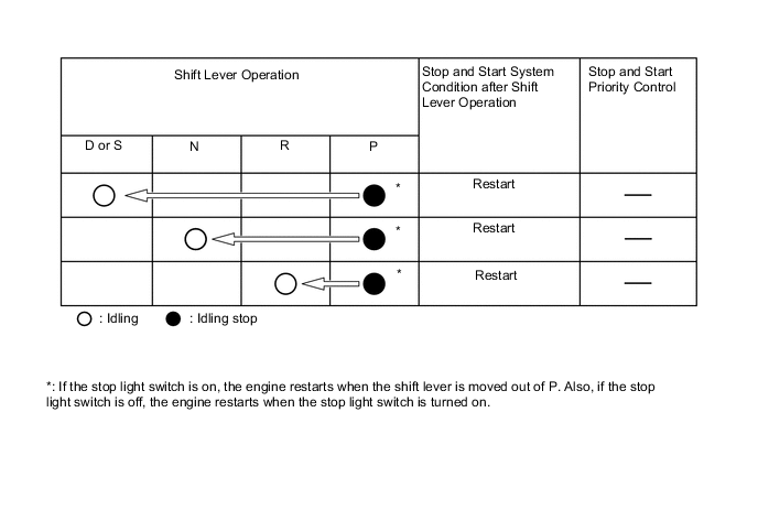
The stop and start system performs the following controls based on the shift lever operation and situation. Furthermore, the condition of the stop and start system after the shift lever is operated may change depending on the vehicle condition and surrounding environment.
Figure 1. Shift Lever in D or S while Idling
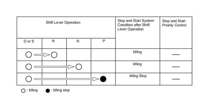
Figure 2. Shift Lever in D or S and Current Idling Stop Time Less than 2 Seconds
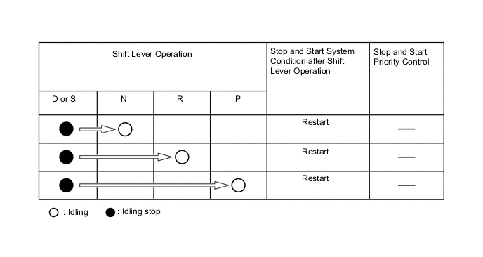
Figure 3. Shift Lever in D or S and Current Idling Stop Time 2 Seconds or More
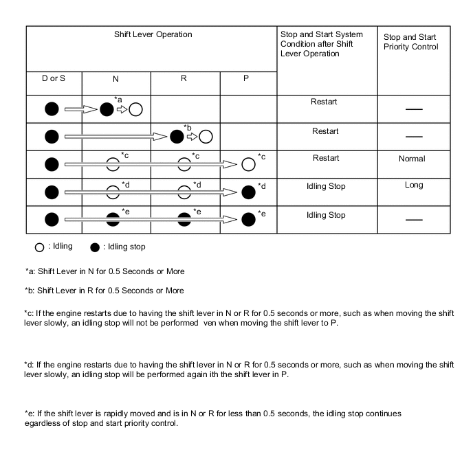
Figure 4. Shift Lever in P during Idling Stop
-
-
-
DIAGNOSIS
-
When the engine stop and start ECU detects a malfunction and CAN communication is normal, the engine stop and start ECU records information related to the malfunction. Furthermore, the stop and start cancel indicator light in the combination meter assembly blinks to inform the driver that CAN communication is normal.
-
The engine stop and start ECU also stores Diagnostic Trouble Codes (DTCs) related to malfunctions. DTCs can be read using the Global TechStream (GTS).
-