NAVIGATION SYSTEM, Diagnostic DTC:B15D8
| DTC Code | DTC Name |
|---|---|
| B15D8 | Monitor Disconnected |
DESCRIPTION
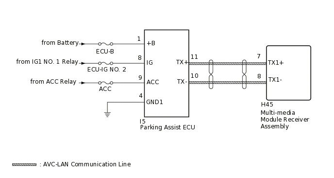
The parking assist ECU and multi-media module receiver assembly are connected by an AVC-LAN communication line. When an AVC-LAN communication error occurs between the multi-media module receiver assembly and parking assist ECU, these DTCs will be stored.
DTC No. |
Detection Item |
DTC Detection Condition |
Trouble Area |
|---|---|---|---|
B15D8 |
Monitor Disconnected |
A device that is listed in the AVC-LAN connected device record of the master unit is missing.* |
|
*: Even if no fault is present, this DTC may be stored depending on the battery condition or engine start voltage.
The multi-media module receiver assembly is the master unit.
WIRING DIAGRAM
CAUTION / NOTICE / HINT
Inspect the fuses for circuits related to this system before performing the following inspection procedure.
PROCEDURE
CLEAR DTC
Clear the DTCs.
Body Electrical > Navigation System > Clear DTCs
Result
Proceed to
NEXT
CHECK DTC
Recheck for DTCs and check if the same DTC is output again.
Body Electrical > Navigation System > Trouble Codes
OK
No DTCs are output.
Result
Proceed to
OK
NG
CHECK HARNESS AND CONNECTOR (PARKING ASSIST ECU - BATTERY AND BODY GROUND)
-
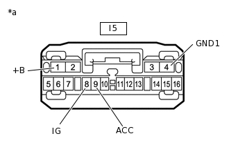
*a
Front view of wire harness connector
(to Parking Assist ECU)
Disconnect the parking assist ECU connector.
Measure the resistance according to the value(s) in the table below.
Standard Resistance
Tester Connection
Condition
Specified Condition
I5-4 (GND1) - Body ground
Always
Below 1 Ω
Measure the voltage according to the value(s) in the table below.
Standard Voltage
Tester Connection
Condition
Specified Condition
I5-1 (+B) - I5-4 (GND1)
Always
11 to 14 V
I5-8 (IG) - I5-4 (GND1)
Engine switch on (IG)
11 to 14 V
I5-9 (ACC) - I5-4 (GND1)
Engine switch on (ACC)
11 to 14 V
Result
Proceed to
OK
NG
NG REPAIR OR REPLACE HARNESS OR CONNECTOR
-
INSPECT MULTI-MEDIA MODULE RECEIVER ASSEMBLY
-
Remove the multi-media module receiver assembly.
Measure the resistance according to the value(s) in the table below.
Standard Resistance
Tester Connection
Condition
Specified Condition
7 (TX1+) - 8 (TX1-)
Always
60 to 80 Ω
Result
Proceed to
OK
NG
-
CHECK HARNESS AND CONNECTOR (MULTI-MEDIA MODULE RECEIVER ASSEMBLY - PARKING ASSIST ECU)
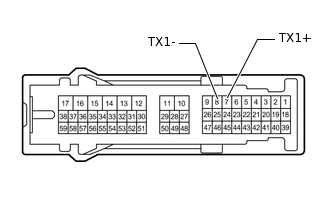
Disconnect the H45 multi-media module receiver assembly connector.
Disconnect the I5 parking assist ECU connector.
Measure the resistance according to the value(s) in the table below.
Standard Resistance
Tester Connection
Condition
Specified Condition
H45-7 (TX1+) - I5-11 (TX+)
Always
Below 1 Ω
H45-8 (TX1-) - I5-10 (TX-)
Always
Below 1 Ω
H45-7 (TX1+) - Body ground
Always
10 kΩ or higher
H45-8 (TX1-) - Body ground
Always
10 kΩ or higher
Result
Proceed to
OK
NG
NG REPAIR OR REPLACE HARNESS OR CONNECTOR
REPLACE PARKING ASSIST ECU
Replace the parking assist ECU with a new or normally functioning one.
Result
Proceed to
NEXT
CLEAR DTC
Clear the DTCs.
Body Electrical > Navigation System > Clear DTCs
Result
Proceed to
NEXT
CHECK DTC
Recheck for DTCs and check if the same DTC is output again.
Body Electrical > Navigation System > Trouble Codes
OK
No DTCs are output.
Result
Proceed to
OK
NG
OK END (PARKING ASSIST ECU IS DEFECTIVE)