FRONT SUSPENSION SYSTEM
-
CONSTRUCTION
-
Front Suspension Support Sub-assembly and Front Coil Spring
-
A split-input type structure is adopted for the front suspension support sub-assembly to ensure excellent quietness and ride comfort.
-
While driving, the input from the tires is transferred to the body via the front shock absorber assembly, front spring bumper and front coil spring. With a split-input type structure, the input from the front shock absorber assembly and front spring bumper is transferred to the body via the rubber portion of the front suspension support sub-assembly. The input from the front coil spring is transferred to the body via the strut mounting bearing. The input from the front shock absorber assembly and front spring bumper, and the input from the front coil spring are received separately, realizing excellent quietness and ride comfort.
-
A pigtail type front coil spring, where the top and bottom diameters are different is used creating a compact and lightweight construction. Lateral force reduction springs are used to control the reaction force line of the front coil spring, and reduce the bending force applied to the front shock absorber assembly. This reduces suspension friction, realizing a very comfortable ride.
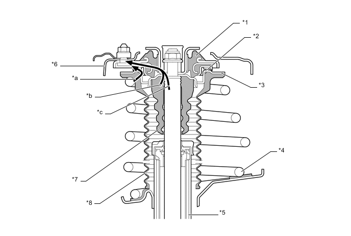
Text in Illustration *1 Front Suspension Support Sub-assembly *2 Strut Mounting Bearing *3 Front Coil Spring Seat Upper *4 Front Coil Spring *5 Front Shock Absorber Assembly *6 Body *7 Front Spring Bumper *8 Front Coil Spring Insulator Upper *a Front Coil Spring Input *b Front Spring Bumper Input *c Front Shock Absorber Assembly Input - -
-
-
Front Shock Absorber Assembly
-
Low-friction oil and oil seals are adopted for the front shock absorber assembly, ensuring damping responsiveness, and realizing a supple ride.
-
A low pressure N2gas charge and saturated type piston valve is adopted for the front shock absorber assembly, contributing to a high level of maneuverability, stability and ride comfort.
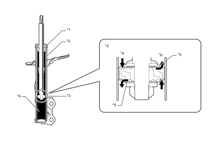
Text in Illustration *1 Oil Seal *2 Low-pressure N2Gas
*3 Saturated Type Piston Valve *4 Oil *5 Orifice - - *a Extension *b Compression Note
To prevent hazardous conditions, make sure to empty the gas from the shock absorber before discarding an N2gas sealed shock absorber. For details, refer to the Repair Manual.
-
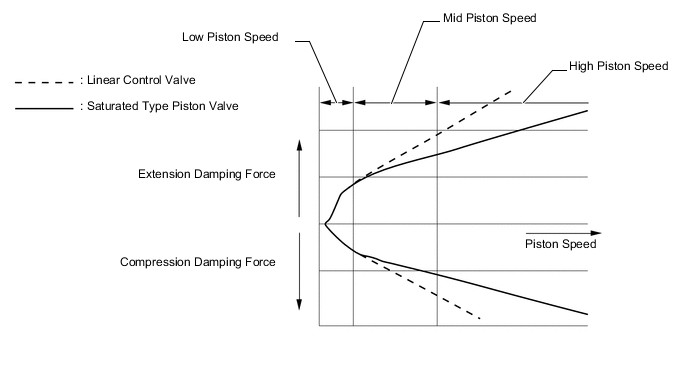
The characteristics of saturated type piston valve are as follows:
-
The orifices are tuned to optimize body control in the low speed (piston speed) damping range.
-
Valve preload is tuned to optimize control of vehicle body movement in the mid speed (piston speed) damping range.
-
The oil passages in the piston have been enlarged to decrease the damping force, thereby reducing the shocks due to impacts in the high speed (piston speed) damping range.
-
-
-
Front Lower Suspension Arm Sub-assembly
-
An L-shaped front lower No. 1 suspension arm sub-assembly, of which the cross section structure is closed, is provided. As a result, in addition to the material thickness having been made thinner, the cross section and arm shape have been optimized, thus, achieving a lightweight yet highly rigid design.
-
The installation point of the lower arm bushes and the bushing characteristics have been optimized to achieve excellent ride comfort and steering characteristics.
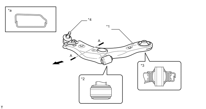
Text in Illustration *1 Front Lower No. 1 Suspension Arm Sub-assembly *2 Front Lower No. 1 Arm Bush (Cross Section) *3 Front Lower No. 2 Arm Bush (Cross Section) *4 Front Lower Ball Joint Assembly *a A-A Cross Section - - 
Front - -
-
-
Front Stabilizer Bar
-
The front stabilizer bar is hollow, reducing weight. A ball joint is used between the front stabilizer link assembly and the front stabilizer bar, and between the front stabilizer link assembly and the front shock absorber assembly. This helps reduce suspension friction and increase link rigidity. As a result, the ball joints perform effectively even for small amounts of roll and maintain stable roll feeling.
-
An aluminum front stabilizer link assemblies are used to achieve weight reduction.
-
To reduce friction, a fluorine coating is provided in the bore of the front stabilizer bar bush.
-
The front stabilizer bar bush is provided with a dust lip to prevent sand from entering.
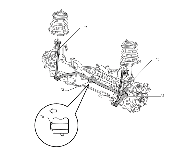
Text in Illustration *1 Front Stabilizer Link Assembly *2 Front Stabilizer Bar *3 Front Stabilizer Bar Bush - - *a Dust Lip - - 
Outside of the Vehicle - - Note
To install the front stabilizer bar bushes on the vehicle, face the dust lips outward.
-
-
Front Suspension Crossmember Sub-assembly
-
A pressed-steel front suspension crossmember sub-assembly is provided.
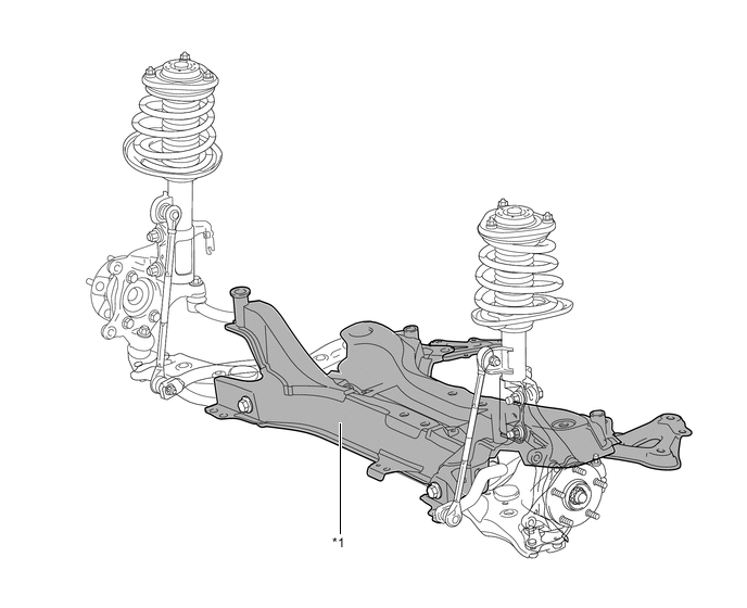
Text in Illustration *1 Front Suspension Crossmember Sub-assembly - -
-
-