REAR DIFFERENTIAL CARRIER ASSEMBLY INSTALLATION

CAUTION / NOTICE / HINT
CAUTION:
The rear differential carrier assembly with differential support is very heavy. Be sure to follow the procedure described in the repair manual, or the engine lifter may suddenly drop.
Note
If installing a new rear differential carrier assembly, remove the 2 differential side seal caps before installing the rear drive shaft assembly.
PROCEDURE
-
TEMPORARILY INSTALL NO. 2 REAR DIFFERENTIAL SUPPORT
-
Temporarily install the No. 2 rear differential support to the rear differential carrier assembly with 2 new bolts and 2 new nuts.
Note
-
Be sure to install the No. 2 rear differential support facing the direction shown in the illustration.
-
Be sure to install the tab of each nut to the position (A) shown in the illustration.
Tech Tips
The nuts have tabs to prevent them from rotating.
-
-
-
INSTALL UPPER REAR DIFFERENTIAL MOUNT STOPPER
-
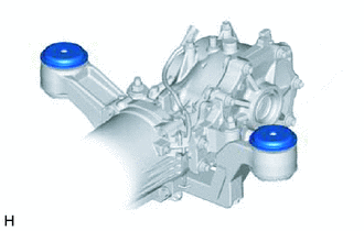
Install the 2 upper rear differential mount stoppers to the No. 2 rear differential support.
Note
Keep the upper rear differential mount stoppers free of oil and foreign matter.
-
-
INSTALL DIFFERENTIAL SUPPORT
-
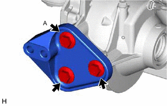
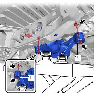
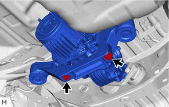
Install the differential support to the rear differential carrier assembly with 3 new bolts.
- Torque:
- 166.7 N*m { 1700 kgf*cm, 123 ft.*lbf }
Note
Tighten the bolt (A) shown in the illustration first.
-
-
TEMPORARILY INSTALL REAR DIFFERENTIAL CARRIER ASSEMBLY WITH DIFFERENTIAL SUPPORT
Note
-
Do not damage the contact surface when installing the rear differential carrier assembly with differential support.
-
The remaining oil may leak out when installing the rear differential carrier assembly with differential support.
-
Securely support the rear differential carrier assembly with differential support while performing this step to avoid excessively tilting or dropping the rear differential carrier assembly with differential support.
-
Install the bolts and nuts with the rear differential carrier assembly with differential support secured.
-
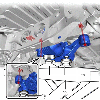
*a Attachment *b Engine Lifter Support the rear differential carrier assembly with differential support with an engine lifter using 3 attachments or equivalent tools as shown in the illustration.
Tech Tips
Raise the rear differential carrier assembly with differential support until the vacuum hose can be installed.
-
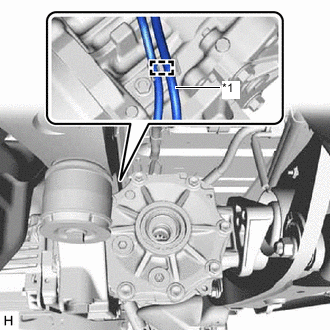
*1 Vacuum Hose Install the vacuum hose to the clamp.
Note
Do not damage the vacuum hose and electro magnetic control coupling wire harness.
-
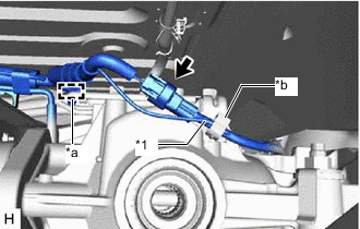
*1 Vacuum Hose *a Clamp (A) *b Clamp (B) Install the vacuum hose to the clamp (B).
-
Connect the connector and engage the clamp (A).
-
*1 Lower Rear Differential Mount Stopper Temporarily install the rear differential carrier assembly with differential support to the front side of the rear suspension member sub-assembly with the 2 lower rear differential mount stoppers, 2 new bolts and 2 new nuts.
Note
Keep the bolt and lower rear differential mount stoppers free of oil and foreign matter.
Tech Tips
-
Be sure to install the lower rear differential mount stoppers with the convex side facing upward.
-
Make sure that the lower rear differential mount stoppers and the upper rear differential mount stoppers are not misaligned or tilted.
-
The nuts have tabs to prevent them from rotating.
-
Raise the engine lifter to the extent that the rear differential carrier assembly with differential support can be temporarily installed.
-
-
-
FULLY INSTALL REAR DIFFERENTIAL CARRIER ASSEMBLY WITH DIFFERENTIAL SUPPORT
Note
Do not tighten the bolts with the inner cylinder or rear differential mount cushion tilted.
-
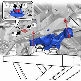
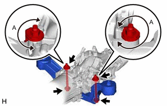
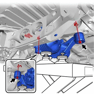
*A for 8AR-FTS for 8AR-FTS:
-
Install the rear differential carrier assembly with differential support and rear differential dynamic damper to the rear No. 2 differential mount cushion with the 2 new bolts (A).
- Torque:
- 95.1 N*m { 970 kgf*cm, 70 ft.*lbf }
-
-
for 2GR-FKS:
-
Install the rear differential carrier assembly with differential support to the rear No. 2 differential mount cushion with the 2 new bolts (B).
- Torque:
- 95.1 N*m { 970 kgf*cm, 70 ft.*lbf }
-
-
Tighten the 2 bolts.
- Torque:
- 86 N*m { 877 kgf*cm, 63 ft.*lbf }
Tech Tips
-
Tighten the bolts only if the No. 2 rear differential support has been removed from the rear differential carrier assembly.
-
Lower the engine lifter to the extent that the bolts can still be tightened.
-
Tighten the 2 bolts.
- Torque:
- 80 N*m { 816 kgf*cm, 59 ft.*lbf }
-
Lower the engine lifter.
-
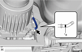
*a Paint Mark Connect the vacuum hose to the electro magnetic control coupling sub-assembly.
Note
Connect the vacuum hose until it reaches the paint mark.
-
-
INSTALL REAR DIFFERENTIAL DRAIN PLUG
-
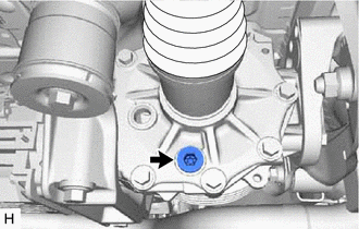
Using a 10 mm hexagon wrench, install a new gasket and the rear differential drain plug.
- Torque:
- 39 N*m { 398 kgf*cm, 29 ft.*lbf }
-
-
INSTALL REAR STABILIZER BAR
w/o Rear No. 2 Seat: Click here
w/ Rear No. 2 Seat: Click here
-
INSTALL PROPELLER WITH CENTER BEARING SHAFT ASSEMBLY
Tech Tips
The inspection and adjustment of the joint angle is performed at the end of the installation procedure.
-
INSTALL REAR DRIVE SHAFT ASSEMBLY
-
Install the rear drive shaft assembly LH and RH.
-
-
INSPECT AND ADJUST JOINT ANGLE