WINDOW DEFOGGER SYSTEM Rear Window Defogger System does not Operate
| DTC Code | DTC Name |
|---|---|
| Rear Window Defogger System does not Operate |
DESCRIPTION
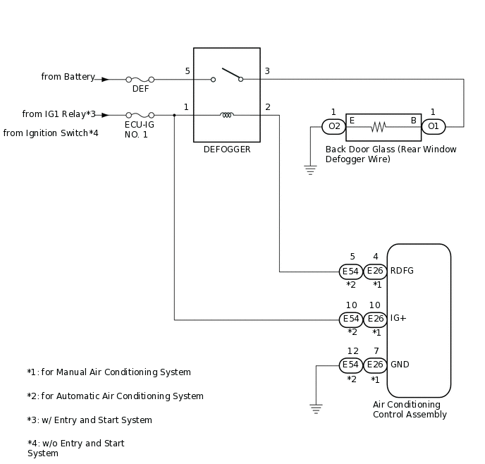
When the rear window defogger switch on the air conditioning control assembly is pressed, the rear window defogger wire becomes warm.
WIRING DIAGRAM
CAUTION / NOTICE / HINT
Inspect the fuses for circuits related to this system before performing the following procedure.
PROCEDURE
CHECK AIR CONDITIONING SYSTEM
Check the air conditioning system.
Tip:Both the window defogger system operation signal and air conditioning system operation signal are transmitted to the air conditioning control assembly via the same communication line.
OK
The air conditioning system operates normally.
Result
Proceed to
OK
NG
INSPECT DEFOGGER RELAY
Remove the defogger relay from CTR relay block.
Inspect the defogger relay.
Result
Proceed to
OK
NG
NG REPLACE DEFOGGER RELAY
CHECK HARNESS AND CONNECTOR (DEFOGGER RELAY HOLDER - POWER SOURCE)
-
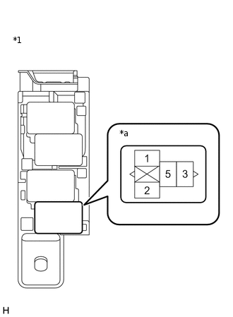
*1
CTR Relay Block
*a
Defogger Relay Holder
Measure the voltage according to the value(s) in the table below.
Standard Voltage
Tester Connection
Condition
Specified Condition
Defogger relay holder terminal-1 - Body ground
Ignition switch ON
11 to 14 V
Result
Proceed to
OK
NG
NG REPAIR OR REPLACE HARNESS OR CONNECTOR
-
CHECK HARNESS AND CONNECTOR (DEFOGGER RELAY HOLDER - BATTERY)
-
*1
CTR Relay Block
*a
Defogger Relay Holder
Measure the voltage according to the value(s) in the table below.
Standard Voltage
Tester Connection
Condition
Specified Condition
Defogger relay holder terminal-3 - Body ground
Always
11 to 14 V
Result
Proceed to
OK
NG
NG REPAIR OR REPLACE HARNESS OR CONNECTOR
-
CHECK HARNESS AND CONNECTOR (DEFOGGER RELAY HOLDER - AIR CONDITIONING CONTROL ASSEMBLY)
-
*1
CTR Relay Block
*a
Defogger Relay Holder
Disconnect the E26*1 or E54*2 air conditioning control assembly connector.
*1: for Manual Air Conditioning System
*2: for Automatic Air Conditioning System
Measure the resistance according to the value(s) in the table below.
Standard Resistance
Table 1. for Manual Air Conditioning System Tester Connection
Condition
Specified Condition
Defogger relay holder terminal-2 - E26-4 (RDFG)
Always
Below 1 Ω
Defogger relay holder terminal-2 or E26-4 (RDFG) - Body ground
Always
10 kΩ or higher
Table 2. for Automatic Air Conditioning System Tester Connection
Condition
Specified Condition
Defogger relay holder terminal-2 - E54-5 (RDFG)
Always
Below 1 Ω
Defogger relay holder terminal-2 or E54-5 (RDFG) - Body ground
Always
10 kΩ or higher
Result
Proceed to
OK
NG
NG REPAIR OR REPLACE HARNESS OR CONNECTOR
-
CHECK AIR CONDITIONING CONTROL ASSEMBLY
-
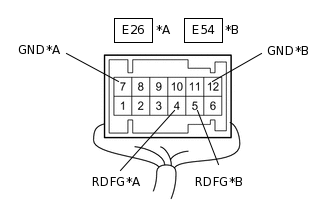
*A
for Manual Air Conditioning System
*B
for Automatic Air Conditioning System
*a
Component with harness connected
(Air Conditioning Control Assembly)
Reconnect the E26*1 or E54*2 air conditioning control assembly connector.
*1: for Manual Air Conditioning System
*2: for Automatic Air Conditioning System
Reinstall the defogger relay.
Measure the voltage according to the value(s) in the table below.
Standard Voltage
Table 3. for Manual Air Conditioning System Tester Connection
Condition
Specified Condition
E26-4 (RDFG) - E26-7 (GND)
Ignition switch ON, rear window defogger switch off
11 to 14 V
E26-4 (RDFG) - E26-7 (GND)
Ignition switch ON, rear window defogger switch on
Below 1 V
Table 4. for Automatic Air Conditioning System Tester Connection
Condition
Specified Condition
E54-5 (RDFG) - E54-12 (GND)
Ignition switch ON, rear window defogger switch off
11 to 14 V
E54-5 (RDFG) - E54-12 (GND)
Ignition switch ON, rear window defogger switch on
Below 1 V
Result
Proceed to
OK
NG
NG REPLACE AIR CONDITIONING CONTROL ASSEMBLY
for Manual Air Conditioning System:Click here
for Automatic Air Conditioning System:Click here
-
CHECK HARNESS AND CONNECTOR (BACK DOOR GLASS (REAR WINDOW DEFOGGER WIRE) - DEFOGGER RELAY HOLDER AND BODY GROUND)
-
*1
CTR Relay Block
*a
Defogger Relay Holder
Disconnect the O1 and O2 back door glass (rear window defogger wire) connectors.
Measure the resistance according to the value(s) in the table below.
Standard Resistance
Tester Connection
Condition
Specified Condition
O1-1 (B) - Defogger relay holder terminal-3
Always
Below 1 Ω
O1-1 (B) or Defogger relay holder terminal-3 - Body ground
Always
10 kΩ or higher
O2-1 (E) - Body ground
Always
Below 1 Ω
Result
Proceed to
OK
NG
NG REPAIR OR REPLACE HARNESS OR CONNECTOR
-
INSPECT BACK DOOR GLASS (REAR WINDOW DEFOGGER WIRE)
Inspect the back door glass (rear window defogger wire).
Result
Proceed to
OK
NG