AUTOMATIC TRANSMISSION SYSTEM
-
SYSTEM CONTROL
Electronic Control of Automatic Transmission Control Function Line Pressure Control Actuates the shift solenoid valve SLT to control the line pressure in accordance with information from the transmission control ECU assembly and the operating conditions of the transmission. Clutch Pressure Optimal Control The shift solenoid valves SL1 and SLT minutely control the clutch pressure in accordance with the engine output and driving conditions of the transmission. Clutch to Clutch Pressure Control Controls the pressure that is applied directly to B2brake and C3clutch by actuating the shift solenoid valves SL1 and SL2 in accordance with the transmission control ECU assembly signals.
Orifice Switching Control
-
Lubricant orifice switching control has been newly adopted in order to ensure reliable air intake performance at extremely low temperatures. It minimizes lubrication amounts while stopped in 1st gear only and not in reverse.
-
Switches to lubricant orifices only while stopped in 1st gear, and otherwise supplies lubricant from one or both lubricant orifices.
Coast Downshift Control To prevent engine speed from decreasing and thereby maintain fuel cut, the transmission control ECU assembly performs downshifts before fuel cut ends. Lock-up Timing Control While in 5th or 6th gear when the shift lever is in D position is selected, the transmission control ECU assembly sends current to the shift solenoid valve SLU based on the signals from the sensors and engages or disengages the lock-up clutch. Flex Lock-up Clutch Control
-
Controls the solenoid valve SLU, provides an intermediate mode between the ON/OFF operation of the lock-up clutch, and increases the operating range of the lock-up clutch to improve fuel economy.
-
The flex lock-up clutch control operates in 4th, 5th and 6th gears in the D position. (Except when in SPORT mode.)
Multi-mode Automatic Transmission
-
The automatic transmission will be controlled at the range position selected while the shift lever is in M.
-
Operating the paddle shift switch (transmission shift switch assembly) with the shift lever in the D position enables D position fixed range mode.
Slope Control Suppresses frequent gear shifting due to operation of the accelerator pedal by the driver while on sloping roads, improving vehicle controllability and trafficability. Downshift Control While Braking Performs a dynamic downshift that is earlier and quicker than during normal driving, in order to add the engine-brake feel while entering corners and to prepare re-acceleration when coming out of corners, improving drivability and handling during sport driving. Cornering Control Whenever the vehicle is detected to be taking a corner, this feature suppresses the upshifting that accompanies vehicle acceleration while taking the corner, preventing fluctuation in vehicle power to improve drivability and handling. Gear Hold Control During Accelerator Pedal Control Whenever the accelerator pedal is returned with a certain speed or higher after being in the pressed state, this feature maintains the selected gear without performing an upshift to improve drivability and handling. Driver Intent Response Control Estimates the driver's intent from accelerator pedal operation and vehicle state to change shift patterns without any incompatibility with the individual driver and without any the operation of any switches. Blipping Downshift Control
-
This system provides integrated control of the hydraulic control system, which directly controls clutch pressure, and the engine and transmission power train.
-
This feature uses the direct hydraulic pressure control system to immediately release the release clutch and create a neutral state. It immediately raises the engine revolution count up to post-acceleration gear synchronous rotation to improve drivability and handling during sport driving without losing the engine-brake feel during speed changes.
Upshift Control for Over-Rev Prevention To prevent excessive engine revving, this feature automatically performs an upshift whenever the engine revolution count exceeds the prescribed revolution count. Downshift Control While Cruise Controlling Whenever cruise control is on and the difference in vehicle speed between the vehicle's actual speed and the set cruise-control speed exceeds the prescribed value, e.g. when driving downhill, this feature automatically shifts down to improve the ability to keep the vehicle speed at the set cruise-control speed.
-
Line Pressure Control
-
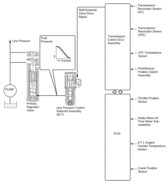
In order to obtain a predetermined line pressure characteristic in accordance with each sensor signal, the ECM activates the shift solenoid valve SLT to regulate the throttle pressure.
-
This makes it possible for the primary regulator valve to precisely and minutely control the line pressure in accordance with the engine output, thus providing smoother shift characteristics.
-
-
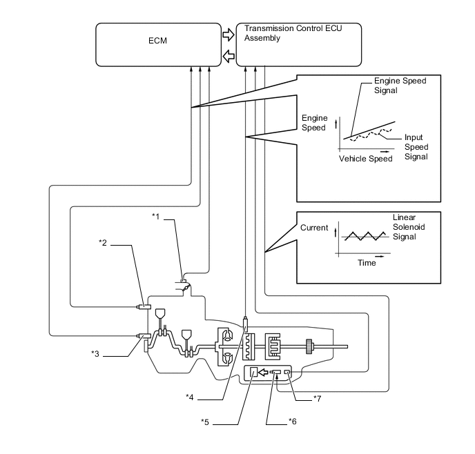
Clutch Pressure Optimal Control
-
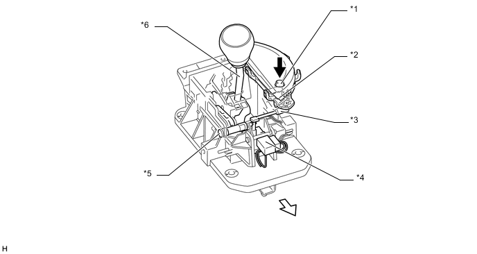
The ECM monitors the signals from various types of sensors, such as the transmission revolution sensor (NT), allowing shift solenoid valves SL1 and SLT to minutely control the clutch pressure in accordance with engine output and driving conditions. As a result, smooth shift characteristics are achieved.
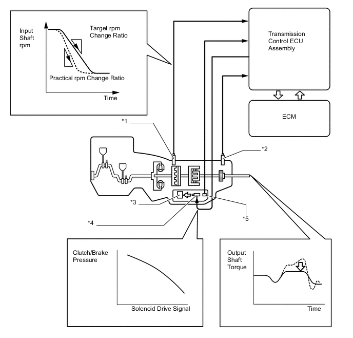
Text in Illustration *1 Transmission Revolution Sensor (NT) *2 Transition Revolution Sensor (SP2) *3 Accumulator Control Valve *4 Shift Solenoid Valve (SL1) and Line Pressure Control Solenoid Assembly (SLT) *5 ATF Temperature Sensor - -
-
-
Clutch to Clutch Pressure Control
-
This control is used for shifting from 5th to 6th gear and from 6th to 5th gear.
-
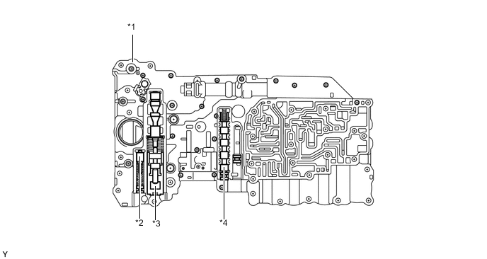
The transmission control ECU assembly actuates shift solenoid valves SL1 and SL2 in accordance with various signals. The output from these shift solenoid valves acts directly on control valves B2and C3in order to regulate the line pressure that acts on the B2brake and C3clutch.
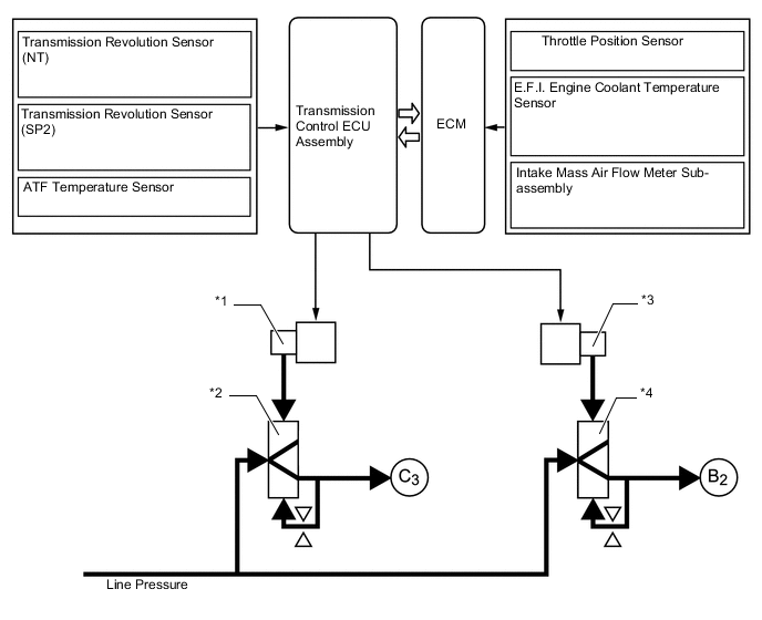
Text in Illustration *1 Shift Solenoid Valve (SL1) *2 Clutch Control Valve *3 Shift Solenoid Valve (SL2) *4 Brake Control Valve
-
-
Orifice Switching Control
-
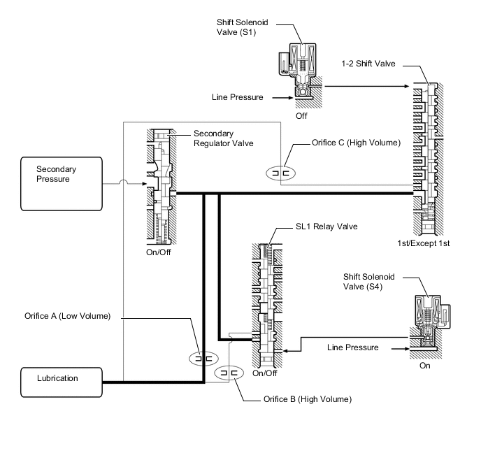
At extremely low temperatures, the ATF viscosity increases (becomes thick), making the oil pump susceptible to cavitation. For this reason, the orifice switching control reduces the volume of ATF in the hydraulic circuit and increases the volume of ATF drawn by the oil pump, in order to prevent the oil pump from cavitating.
-
While stopped in the 1st gear, the transmission control ECU assembly turns off the shift solenoid valve S1 and turns on (normally off) the shift solenoid valve S4 in order to apply the line pressure to the 1-2 shift valve and the SL1 relay valve. The 1-2 shift valve and the SL1 relay valve close the ATF passage for the secondary pressure from the secondary regulator valve, thus causing the secondary pressure to pass through orifice "A". As a result, the volume of ATF in the hydraulic circuit is reduced.
-
While stopped in a gear other than 1st, the secondary pressure from the secondary regulator valve travels through either or both of the 1-2 shift valve and SL1 relay valve, and passes through orifice "B" and "C". As a result, the volume of the ATF in the hydraulic circuit is not reduced.
-
-
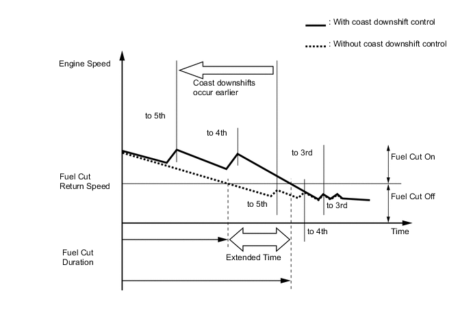
Coast Downshift Control
-
The ECM performs downshift control to prevent the engine speed from decreasing, thus keeping fuel cut control operating for as long as possible. In this way, the fuel economy is improved.
-
For this control, when the vehicle is in 6th gear and starts decelerating, the transmission downshifts from 6th to 5th and from 5th to 4th before fuel cut control ends so that fuel cut control continues operating.
-
-
Lock-up Timing Control
-
The transmission control ECU assembly operates the lock-up timing control in order to improve the fuel consumption performance in the 5th or 6th gear when the shift lever is in the D position.
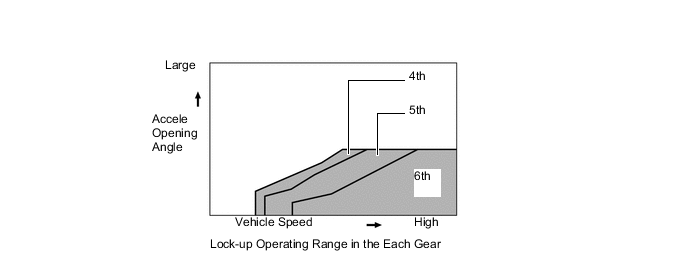
Lock-up Timing Control Operation Range (Gear) Shift Pattern D 1st←→2nd←→3rd←→4th*1←→5th*2←→6th*2 M 1st←→2nd←→3rd←→4th←→5th*2←→6th*2 Tech Tips
*1: Flex lock-up activation (flex lock-up only during acceleration)
*2: Lock-up or flex lock-up activation
-
-
Flex Lock-up Clutch Control
-
In the low-to-mid-speed range, this flex lock-up clutch control regulates the shift solenoid valve SLU to provide an intermediate mode between the on and off operations of the lock-up clutch in order to improve the energy transmitting efficiency. As a result, the operating range of the lock-up clutch has been increased and fuel economy has been improved. The flex lock-up clutch control operates in 4th, 5th and 6th gears in the D position. (Except when in SPORT mode.)
-
The flex lock-up clutch control operates even when the vehicle is decelerating (the accelerator pedal has been released). The fuel cut-off range of the engine has thus been expanded, and fuel economy has been improved.
*1 Throttle Position Sensor *2 E.F.I. Engine Coolant Temperature Sensor *3 Crank Position Sensor *4 Transmission Revolution Sensor (NT) *5 Lock-up Control Valve *6 Lock-up Control Solenoid Assembly (SLU) *7 ATF Temperature Sensor - - 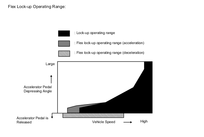
Flex Lock-up Clutch Control Operation Gear Shift Lever Position or Shift Range D M 1st X X 2nd X ○ 3rd X ○ 4th ○ ○ 5th ○*1 ○*1 6th*2 ○*1 ○*1 Tech Tips
○: Operates
X: Does not operate
*1: Flex lock-up clutch control operates during deceleration.
*2: 6th gear is not permitted when A/T oil temperature is less than 20°C.
-
-
Slope Control
If a sloping road is detected by a grade (load) estimation calculated from each sensor value, frequent gear shifting due to the driver's operation of the accelerator pedal is suppressed and vehicle behavior is stabilized, improving controllability and trafficability.
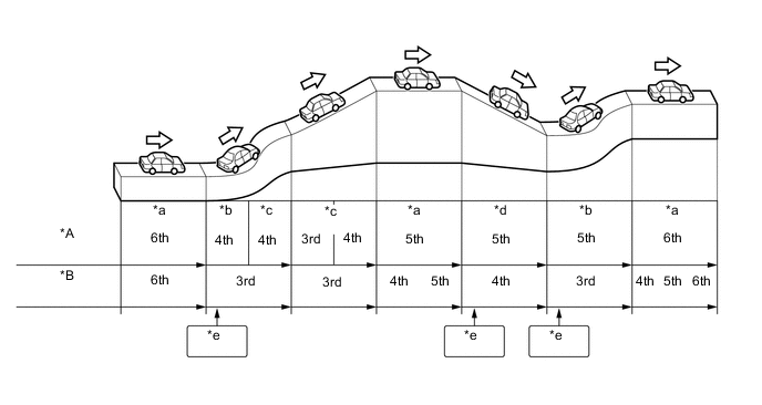
Text in Illustration *A Without Slope Control (Reference) *B With Slope Control *a Level Road *b Corner *c Uphill Road *d Downhill Road *e Brakes On - - -
Downshift Control While Braking
Dynamic downshifting that is earlier and quicker than during normal driving is performed to add the engine-brake feel during heavy braking by the driver while entering a corner and to prepare re-acceleration when coming out of the corner, improving drivability and handling.
-
Cornering Control
Whenever the vehicle is detected to be taking a corner by the yaw rate sensor, which is installed in the skid control computer, the upshifting that occurs as a part of vehicle acceleration is suppressed while the vehicle is taking the corner, preventing fluctuation in vehicle power to improve drivability and handling.
-
Gear Hold Control During Accelerator Pedal Control
Whenever the accelerator pedal is returned with a certain speed or higher after being in the pressed state, this feature maintains the selected gear without performing an upshift to improve drivability and handling.
-
Driver Intent Response Control
Estimates the driver's intent from accelerator pedal operation and vehicle state to change shift patterns without any incompatibility with the individual driver and without any the operation of any switches.
-
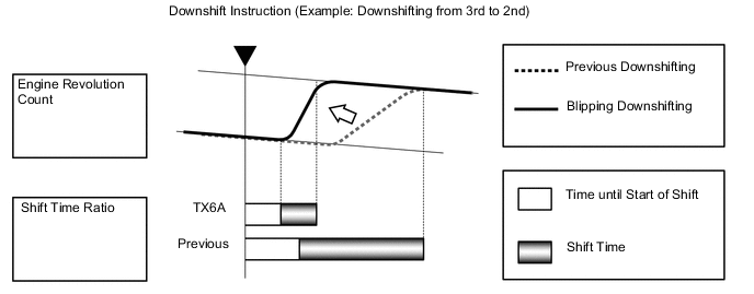
Blipping Downshift Control
-
The TX6A includes a system for integrated control of the engine and transmission power train.
-
The hydraulic control system quickly releases the release-side clutch to produce a neutral state. The integrated power train control opens the throttle valve to immediately increase engine revs all the way to match the post-shift gear. Then, it quickly engages the release-side clutch to achieve a high-response gear shift change.
-
-
Upshift Control for Over-Rev Prevention
To prevent excessive engine revving, this feature automatically performs an upshift whenever the engine revolution count exceeds the prescribed revolution count.
-
Downshift Control While Cruise Controlling
Whenever cruise control is on and the difference in vehicle speed between the vehicle's actual speed and the set cruise-control speed exceeds the prescribed value, e.g. when driving downhill, this feature automatically shifts down to maintain the set cruise control speed, improving drivability.
-
Multi-mode Automatic Transmission
-
Multi-mode automatic transmission is designed to allow the driver to switch between gear ranges. By moving the shift lever to M and then moving the shift lever toward "+" or "-", the driver can select the desired shift range. Thus, the driver is able to shift gears with a manual like feel.
-
A D position (fixed range mode) is used. Operating the shift paddle switch (transmission shift switch assembly) while driving with the shift lever in D will immediately cause the vehicle to enter fixed range mode, which is the same as M mode. As a result, engine braking and downshifts necessary for acceleration are achieved even when driving with the shift lever in D.
-
The default gear when the shift lever is moved from the D position to the M position is the same gear as the gear that was in use while driving in the D position. (No gear shift occurs when the shift lever is moved from the D position to the M position.) The gear position then changes in single-gear increments as the driver moves the shift lever forward (the "+" position) or backward (the "-" position).
-
As with an ordinary automatic transmission, it shifts to the 1st gear when the vehicle is stopped.
-
The sequential shift-matic indicator illuminates when the paddle is operated with the shift lever in the M position or the D position. The shift range indicator indicates the gearshift position that has been selected.
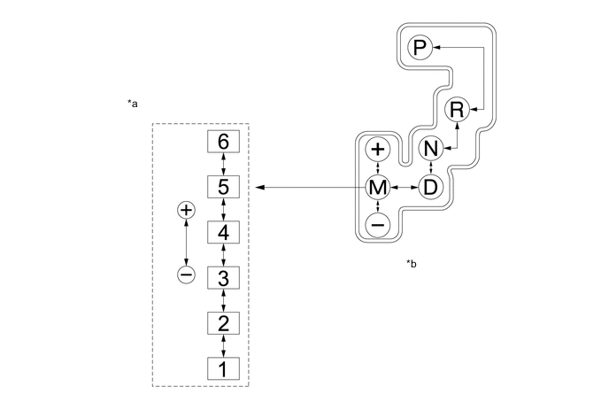
Text in Illustration *a Transition of Shift Ranges *b Shift Pattern Usable Gear Chart Shift Range Shift Range Indicator Display Usable Gear M6 6 6th←→5th←→4th←→3rd←→2nd←→1st M5 5 5th←→4th←→3rd←→2nd←→1st M4 4 4th←→3rd←→2nd←→1st M3 3 3rd←→2nd←→1st M2 2 2nd←→1st M1 1 1st -
When the shift lever is put into the D position, operating the shift paddle switch (transmission shift switch assembly) will put it into temporary M mode (fixed range mode). By operating the shift paddle switches (transmission shift switch assembly) "+" (UP) or "-" (DOWN), the shift range can be changed. At this time, the shift range indicator light in the combination meter assembly changes to inform the driver that the temporary M mode (fixed range mode) has been entered.
-
When one of the following conditions is met, the vehicle will change back to normal D position operation.
- The vehicle is stopped or less than 9 km/h (5.6 mph).
- The accelerator pedal is continually pressed while traveling straight. (The time depends on the driving state.)
-
When the accelerator pedal is pressed until fully open.
-
When the accelerator pedal is pressed for a set period of time or longer. (The time depends on the driving state.)
Usable Gear Chart Shift Range Shift Range Indicator Indication Usable Gear D6 6 6th ←→ 5th ←→ 4th ←→ 3rd ←→ 2nd ←→ 1st D5 5 5th ←→ 4th ←→ 3rd ←→ 2nd ←→ 1st D4 4 4th ←→ 3rd ←→ 2nd ←→ 1st D3 3 3rd ←→ 2nd ←→ 1st D2 2 2nd ←→ 1st D1 1 1st -
-
-
-
FUNCTION
-
Shift Paddle Switch (Transmission Shift Switch Assembly)*
-
When the shift lever is in M, the shift ranges can be selected by using the shift paddle switches (transmission shift switch assembly) located behind the steering wheel. Then, the shift range positions change one at a time, as the driver pulls the right shift paddle switch (transmission shift switch assembly) (+ position) or to the left one (- position).
-
Operating the shift paddle switch (transmission shift switch assembly) with the shift lever in D enables use of the temporary M mode (fixed range mode). Temporary M mode (fixed range mode) allows a fixed range mode identical to the M position with the shift lever remaining in D.
-
*: Models with paddle shift switch (transmission shift switch assembly)
-
-
-
Pattern Select Switch Assembly
-
The ECT pattern select switch is located on the rear of the shift lever. The driver can switch between SPORT Mode and SNOW Mode by operating the switch.
-
In SPORT mode, the transmission control computer boosts acceleration and responsiveness through active control and by taking over active operation the transmission shift points and lock-up state from normal mode, in order to accommodate sporty driving.
-
SNOW mode enables driving on snow and other slippery surfaces via the transmission control computer.
-
-
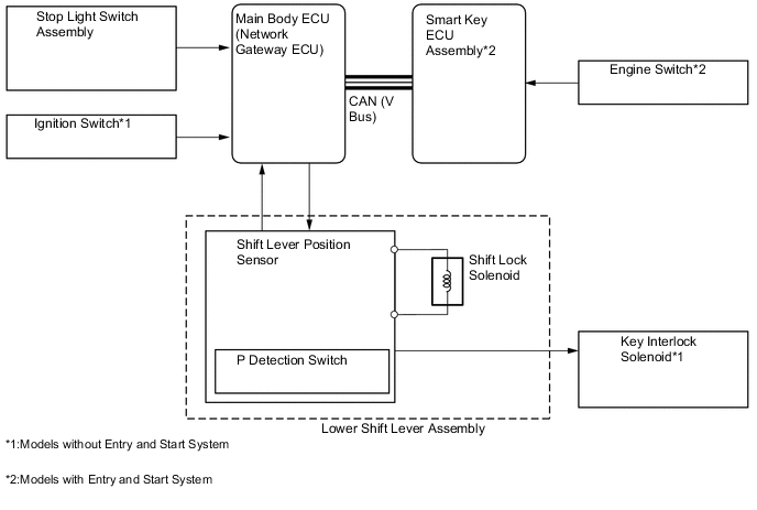
Shift Lock System
-
On models without a smart entry and start system, the key interlock device prevents the key from being pulled out after the ignition switch has been turned off, unless the shift lever has been moved to P. Thus, the driver is urged to park the vehicle with the shift lever in P.
-
The shift lock mechanism prevents the shift lever from being moved to a position other than P when the ignition switch is on, if the brake pedal is also not in being depressed. This is to prevent incorrect operation of the shift lever.
-
The shift lever position sensor uses the P detection switch to detect the position of the gearshift lever. The main body ECU (network gateway ECU) receives an input signal from the stoplight switch assembly and ignition switch*1, and the smart key ECU assembly receives an input signal from the engine switch*2. When these signals are received, the lower shift lever assembly turns on the key interlock solenoid*1 and shift lock solenoid to release the key interlock and shift lock.
-
A shift lock release button, which manually overrides the shift lock mechanism, is used.
-
*1: Models without entry and start system
-
*2: Models with entry and start system
-
-
-
-
CONSTRUCTION
-
Torque Converter Assembly
-
A compact, lightweight and high-capacity torque converter assembly is used. The torque converter supports lock-up clutch control, thus improving fuel economy.
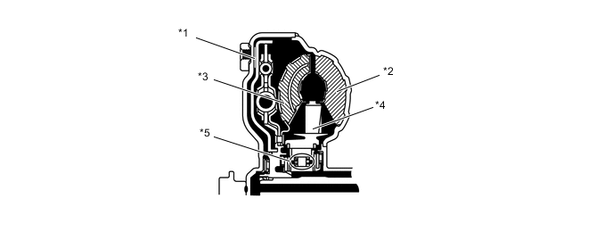
Text in Illustration *1 Lock-up Clutch *2 Pump Impeller *3 Turbine Runner *4 Stator *5 1-way Clutch - -
-
-
Oil Pump
-
The oil pump is operated by the torque converter assembly. It lubricates the planetary gear units and supplies operating fluid pressure for hydraulic control. The front oil pump drive gear is continually driven by the engine via the pump impeller. The pump has sufficient capacity to supply the necessary fluid pressure throughout all speed ranges, as well as in reverse.
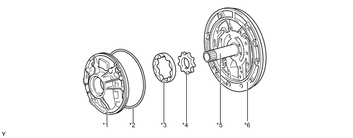
Text in Illustration *1 Front Oil Pump Body Sub-assembly *2 O-ring *3 Front Oil Pump Driven Gear *4 Front Oil Pump Drive Gear *5 Stator Shaft Assembly *6 Oil Pump Cover
-
-
Oil Strainer
-
A felt type oil strainer (in a plastic case) is used because it weighs less, offers excellent debris capturing ability, and is more reliable. This oil strainer is maintenance-free.
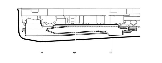
Text in Illustration *1 Plastic Case *2 Felt Strainer *3 Oil Pan - -
-
-
ATF Filling Procedures
-
An ATF filling procedure is used in order to improve the accuracy of the ATF level when the transmission is being repaired or replaced. As a result, the oil filler tube and the oil level gauge used in the conventional automatic transmission have been discontinued, eliminating the need to inspect the fluid level as a part of routine maintenance. For details about the ATF filling procedures, refer to the corresponding Repair Manual for this model.
-
This filling procedure uses a refill plug, overflow plug, ATF temperature sensor and shift position indicator light D.
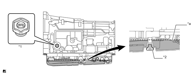
Text in Illustration *1 Refill Plug *2 Overflow Plug *a Proper Level - -
-
-
ATF Warmer
-
A transmission fluid (ATF) warmer has been adopted. It promotes early ATF warm-up and reduces time reduction and friction loss up to flex lock-up control start using a mechanism that does not rely on a general radiator-internal oil cooler. It also ensures excellent fuel economy by functioning as an oil cooler at high temperatures.
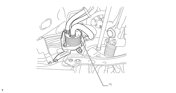
Text in Illustration *1 ATF Warmer (Transmission Oil Cooler Assembly) - -
-
-
Planetary Gear Unit
-
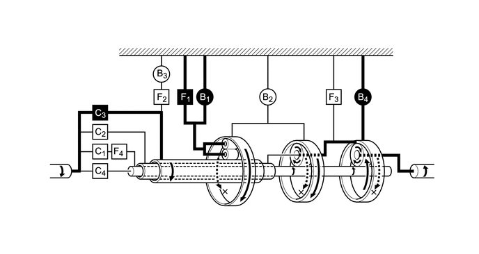
The gear train consists of four multi-plate clutches, four multi-plate brakes, four 1-way clutches, and three sets of planetary gears each consisting of a sun gear, a pinion gear and a ring gear.
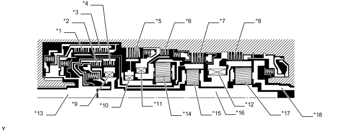
Text in Illustration *1 No. 2 Clutch (C2)
*2 No. 4 Clutch (C4)
*3 No. 3 Clutch (C3)
*4 No. 1 Clutch (C1)
*5 No. 3 Brake (B3)
*6 No. 1 Brake (B1)
*7 No. 2 Brake (B2)
*8 No. 4 Brake (B4)
*9 No. 4 1-way Clutch (F4)
*10 No. 2 1-way Clutch (F2)
*11 No. 1 1-way Clutch (F1)
*12 No. 3 1-way Clutch (F3)
*13 Input Shaft *14 Front Planetary Gear Assembly *15 Center Planetary Gear Assembly *16 Intermediate Shaft *17 Rear Planetary Gear Assembly *18 Output Shaft 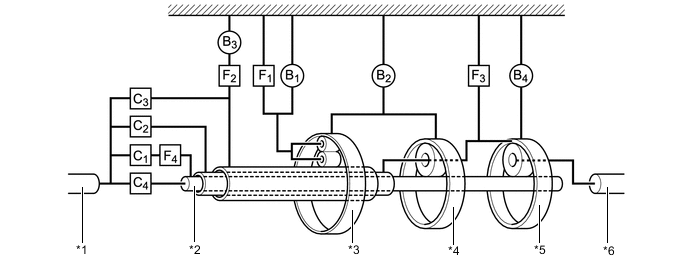
Text in Illustration *1 Input Shaft *2 Intermediate Shaft *3 Front Planetary Gear Assembly *4 Center Planetary Gear Assembly *5 Rear Planetary Gear Assembly *6 Output Shaft -
The functions of the clutches and brakes are as follows:
Component Function C1 No. 1 Clutch Connects the input shaft, F4 and intermediate shaft. C2 No. 2 Clutch Connects the input shaft and center planetary carrier. C3 No. 3 Clutch Connects the input shaft and sun gear. C4 No. 4 Clutch Connects the input shaft and intermediate shaft. B1 No. 1 Brake Prevents the front planetary carrier from turning either clockwise or counterclockwise. B2 No. 2 Brake Prevents the front and the center ring gear from turning either clockwise or counterclockwise. B3 No. 3 Brake Prevents outer race of F2 from turning both clockwise and counterclockwise. B4 No. 4 Brake Prevents center planetary carrier and the rear ring gear from turning either clockwise or counterclockwise. F1 No. 1 One-way Clutch Prevents the front planetary carrier from turning counterclockwise. F2 No .2 One-way Clutch When B3 is operating, the one-way clutch prevents the front sun gear from turning counterclockwise. F3 No. 3 One-way Clutch Prevents the center planetary carrier and the rear ring gear from turning counterclockwise. F4 No. 4 One-way Clutch Prevents the intermediate shaft from turning counterclockwise. Planetary Gears These gears change the route through which driving force is transmitted, in accordance with the operation of each clutch and brake, in order to increase or reduce the output shaft speed.
-
-
Centrifugal Fluid Pressure Canceling Mechanism
-
The centrifugal fluid pressure canceling mechanism is used on the C1, C2, C3and C4clutches that are applied when shifting 2nd-3rd, 3rd-4th, 4th-5th and 5th-6th.
-
Clutch shifting operation is affected not only by the valve body controlling fluid pressure but also by centrifugal fluid pressure that is present due to fluid in the clutch piston oil pressure chamber. The centrifugal fluid pressure canceling mechanism uses chamber B to reduce the affect applied to chamber A. As a result, smooth shifting with excellent response has been achieved.
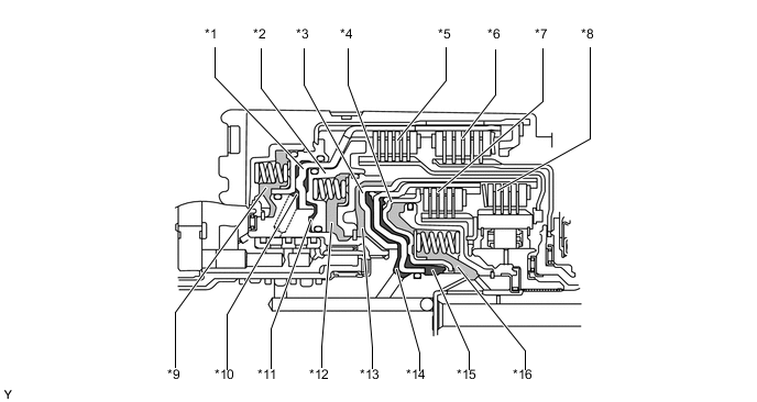
Text in Illustration *1 Piston (for C3)
*2 Piston (for C2)
*3 Piston (for C4)
*4 Piston (for C1)
*5 No. 2 Clutch (C2)
*6 No. 3 Clutch (C3)
*7 No. 4 Clutch (C4)
*8 No. 1 Clutch (C1)
*9 Chamber B (for C3)
*10 Chamber A (for C3)
*11 Chamber A (for C2)
*12 Chamber B (for C2)
*13 Chamber B (for C4)
*14 Chamber A (for C4)
*15 Chamber A (for C1)
*16 Chamber B (for C1)
-
Chamber B is filled by fluid supplied to the shaft for lubrication. As a result of filling chamber B, the same amount of fluid pressure is present on both sides of the piston due to centrifugal force. This cancels the effects of fluid pressure on the piston caused by centrifugal force. Accordingly, it is not necessary to discharge the fluid through the use of a check ball, and highly responsive and smooth shifting characteristics are achieved.
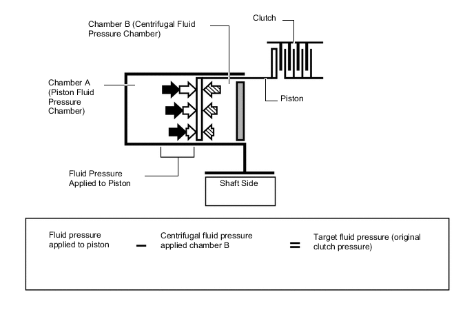
Text in Illustration 
Target fluid pressure 
Centrifugal fluid pressure applied to chamber A 
Centrifugal fluid pressure applied to chamber B - -
-
-
Transmission Valve Body Assembly
-
The transmission valve body assembly consists of the upper (No. 1 and No. 2) and lower (No. 1 and No. 2) valve bodies and 9 shift solenoid valves.
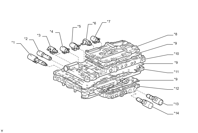
Text in Illustration *1 Line Pressure Control Solenoid Assembly (SLT) *2 Shift Solenoid Valve (SL1) *3 Shift Solenoid Valve (SR) *4 Shift Solenoid Valve (S1) *5 Shift Solenoid Valve (S4) *6 Shift Solenoid Valve (S2) *7 Shift Solenoid Valve (S3) *8 No. 2 Upper Valve Body *9 Plate *10 No. 1 Upper Valve Body *11 No. 1 Lower Valve Body *12 No. 2 Lower Valve Body *13 Lock-up Control Solenoid Assembly (SLU) *14 Shift Solenoid Valve (SL2) 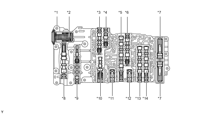
Text in Illustration *1 No. 1 Upper Valve Body *2 C1Accumulator
*3 Clutch Apply Relay Valve *4 Clutch Control Valve *5 1-2 Shift Valve *6 Sequence Valve *7 B2Accumulator
*8 Secondary Regulator Valve *9 Lock-up Relay Valve *10 Lock-up Control Valve *11 C3Check Valve
*12 B4Outer Check Valve
*13 2-3 Valve *14 3-4 Valve 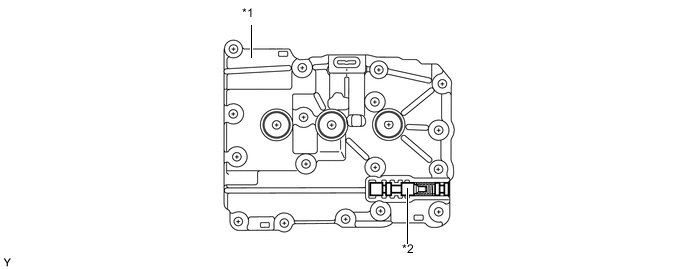
Text in Illustration *1 No. 2 Upper Valve Body *2 C3Apply Relay Valve
Text in Illustration *1 No. 1 Lower Valve Body *2 SLT Damper *3 Primary Regulator Valve *4 4-5 Shift Valve 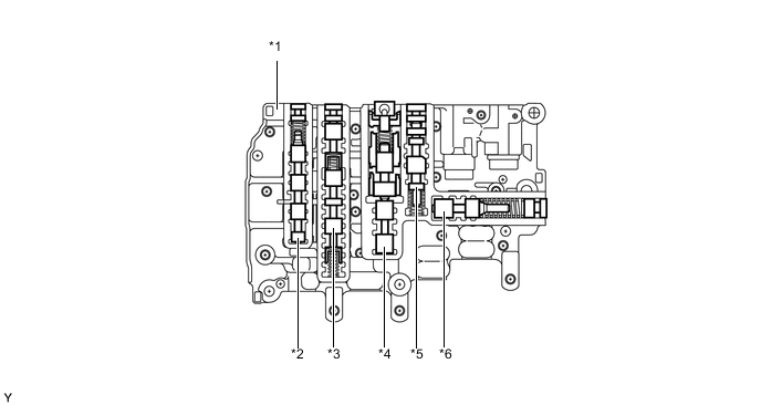
Text in Illustration *1 No. 2 Lower Valve Body *2 B1Apply Relay Valve
*3 Solenoid Relay Valve *4 Accumulator Control Valve *5 Brake Control Valve *6 Solenoid Modulator Valve
-
-
Shift Solenoid Valves S1, S2, S3, S4 and SR
-
The shift solenoid valves S1, S2, S3, S4 and SR are 3-way solenoid valves.
-
A filter is provided at the tip of the solenoid valve to further improve operational reliability.
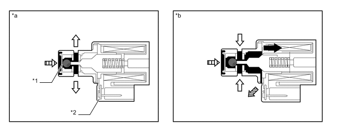
Text in Illustration *1 Filter *2 Shift Solenoid Valves S1, S2, S3 and SR *a Off Condition *b On Condition 
Line Pressure Control Pressure Drain Moving direction of the valve 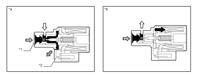
Text in Illustration *1 Filter *2 Shift Solenoid Valve S4 *a Off Condition *b On Condition Line Pressure Control Pressure Drain Moving direction of the valve Function of Shift Solenoid Valves S1, S2, S3, S4 and SR Shift Solenoid Valve Function S1 Switches the 1-2 shift valve and the SL1 relay valve. S2 Switches the 2-3 shift valve and the 5-6 shift valve. S3 Switches the 3-4 shift valve. S4 Switches the 4-5 shift valve , SL1 relay valve and reverse sequence valve. SR Switches the clutch apply relay valve and B1 relay valve.
-
-
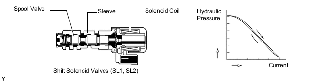
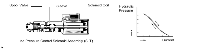
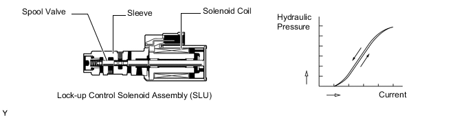
Shift Solenoid Valves SL1, SL2, SLT and SLU
-
Hydraulic pressure for clutch engagement hydraulic control (SL1) and break engagement control (SL2) is supplied in proportional to the electrical current flowing through the solenoid coil. Hydraulic pressure for the clutch is controlled based on signals received from the transmission control computer.
-
In order to provide a hydraulic pressure that is proportional to the current that flows to the solenoid coil, the line pressure control solenoid assembly (SLT) linearly controls the line pressure based on the signals it receives from the transmission control ECU assembly.
-
In order to provide a hydraulic pressure that is proportional to the current that flows to the solenoid coil, the lock-up control solenoid assembly (SLU) linearly controls the lock-up clutch engagement pressure based on the signals it receives from the transmission control ECU assembly.
Function of Shift Solenoid Valves SL1, SL2, SLT and SLU Shift Solenoid Valve Function SL1
-
C1clutch pressure control
-
Accumulator back pressure control
SL2 B1, B2and B4brake pressure control
SLT
-
Line pressure control
-
Accumulator back pressure control
SLU
-
Lock-up clutch pressure control
-
Accumulator back pressure control
-
-
-
ATF Temperature Sensor
-
The ATF temperature sensor is used as an input for hydraulic pressure control. This sensor is used to assist in determining the clutch and brake pressures necessary to maintain smooth shift qualities with varying temperatures of transmission fluid.
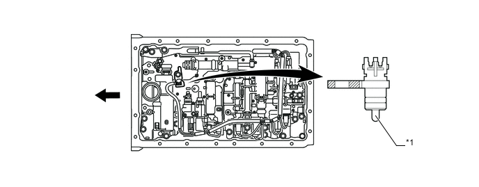
Text in Illustration *1 ATF Temperature Sensor - - Front - -
-
-
Transmission Revolution Sensors
-
This automatic transmission uses a speed sensor NT and speed sensor SP2. Thus, the transmission control ECU assembly can detect the timing of the shifting of the gears and appropriately control the engine torque and hydraulic pressure in response to the various conditions.
-
These transmission revolution sensors are the pick-up coil type.
-
The transmission revolution sensor (for NT signal) detects the input speed of the transmission. The reverse clutch piston sub-assembly is used as the timing rotor for this sensor.
-
The transmission revolution sensor (for SP2 signal) detects the output speed of the transmission. The parking lock gear on the rear planetary gear is used as the timing rotor for this sensor.
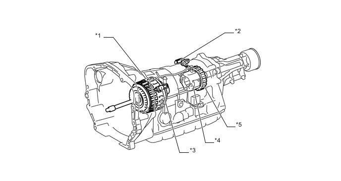
Text in Illustration *1 Reverse Clutch Piston Sub-assembly *2 Transmission Revolution Sensor (SP2) *3 Transmission Revolution Sensor (NT) *4 Rear Planetary Gear *5 Parking Lock Gear - -
-
-
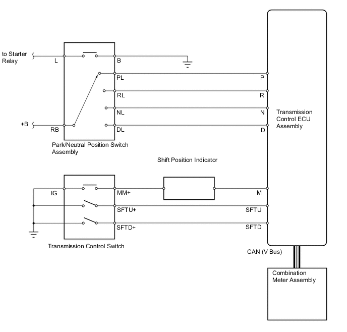
Park/Neutral Position Switch Assembly and Transmission Control Switch
-
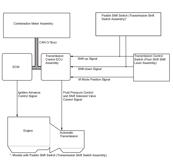
The transmission control ECU assembly uses the park/neutral position switch assembly and the transmission control switch to detect the shift lever position.
-
The park/neutral position switch assembly sends the P, R, N, D signals to the transmission control ECU assembly. The transmission control ECU assembly also sends signals to the shift position indicator light "P, R, N, and D" in the combination meter assembly via CAN.
-
The transmission control switch is installed inside the transmission floor shift assembly to detect the M mode position and to inform the transmission control ECU assembly. The transmission control ECU assembly turns on the M mode indicator light in the combination meter assembly.
-
The transmission control switch detects whether the shift lever is in D or M, and detects the operating conditions of the shift lever ["+" (forwards) or "-" (backwards)] when the M mode is selected, and sends signals to the transmission control ECU assembly. At this time, the transmission control ECU assembly turns on the shift range indicator in the combination meter assembly via CAN for the selected shift range.
-
-
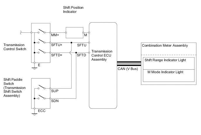
Transmission Control Switch and Shift Paddle Switch
-
The transmission control switch detects whether the shift lever is in D or M, and detects the operating conditions of the shift lever (+ position or - position) if the M mode is selected, and sends signals to the transmission control ECU assembly. At this time, the transmission control ECU assembly turns on the shift range indicator light for the selected range.
-
The shift paddle switches (transmission shift switch assembly) are installed on the steering wheel assembly. The transmission control ECU assembly detects the operating conditions of the shift paddle switches (transmission shift switch assembly) (+ position or - position) when the shift lever is in S. At this time, the transmission control ECU assembly turns on the shift range indicator light for the selected range.
-
-
Shift Lock Mechanism
-
A shift-lock system has been adopted to prevent incorrect use of the shift lever.
-
Control by the main body ECU (network gateway computer) allows the gear to be switched from the P position to another position only while the brake pedal is being pressed when the ignition switch is in the on state.
-
The shift-lock mechanism is composed of the shift lever, shift-lock plate, shift-lock release button, shift-lock manual release plate, shift-lock release rod, and solenoid.
-
The gear cannot be changed from the D position to the R position while driving.
-
During electrical operation, when the brake pedal is pressed, the solenoid releases the shift-lock plate by pulling it.
-
During manual operation, when the shift-lock release button is pressed, the shift-lock manual release plate is pressed, and the solenoid is pressed via the shift-lock release rod to release the shift-lock plate.
Text in Illustration *1 Shift Lock Release Button *2 Shift Lock Manual Release Plate *3 Shift Lock Release Rod *4 Solenoid *5 Shift Lock Plate *6 Shift Lever Front - -
-
-
Automatic Transmission Fluid (ATF) WS
-
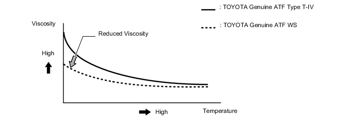
TOYOTA genuine ATF WS is used to reduce the resistance of the ATF and improve the fuel economy by reducing its viscosity in the practical operating temperature range. At higher fluid temperatures, the viscosity is the same as that of TOYOTA genuine ATF Type T-IV, to ensure the durability of the automatic transmission.
-
-
-
OPERATION
-
Transmission Power Flow
Operating Condition of Shift Solenoid Valves Shift Lever Position or Shift Range Gear Position Shift Solenoid Valve S1 S2 S3 S4 SR SL1 SL2 SLU P Park Off On On Off On Off*2 (On)*3 On Off R Reverse Off On On Off On Off*2 (On)*3 On Off N Neutral Off On On Off On Off*2 (On)*3 On Off D 1st Off On On Off On Off On Off 2nd*1 On On On On On Off Off Off 3rd*1 On Off On Off On Off Off Off 4th*1 On Off Off Off On Off On On 5th*1 On Off Off On Off On Off On 6th*1 On On Off On Off On Off On M 1st*1 Off On On Off On Off Off Off 2nd*1 On On On On On Off Off On 3rd*1 On Off On Off On Off Off On 4th*1 On Off Off Off On Off On On 5th*1 On Off Off On Off On Off On 6th*1 On On Off On Off On Off On Tech Tips
*1: Engine braking occurs
*2: Brake Off
*3: Brake On
Operating Condition of Friction Engagement Components and 1-way Clutch Shift Lever Position or Shift Range Gear Position Clutch Brake 1-way Clutch C1
C2
C3
C4
B1
B2
B3
B4
F1
F2
F3
F4
P Park - - - - - - - - - - - - R Reverse - - ○ - ○ - - ○ ○ - - - N Neutral - - - - - - - - - - - - D 1st ○ - - - - - - - - - ○ ○ 2nd* ○ - - ○ - ○ ○ - ○ ○ - ○ 3rd* ○ - ○ ○ ○ - ● - ○ - - ○ 4th* ○ ○ ● ○ - - ● - - - - ○ 5th* ● ○ ○ - ○ - ● - - - - - 6th* ● ○ - - ● ○ ● - - - - - M 1st* ○ - - ○ - - - ○ - - ○ ○ 2nd* ○ - - ○ - ○ ○ - ○ ○ - ○ 3rd* ○ - ○ ○ ○ - ● - ○ - - ○ 4th* ○ ○ ● ○ - - ● - - - - ○ 5th* ● ○ ○ - ○ - ● - - - - - 6th* ● ○ - - ● ○ ● - - - - - Tech Tips
○: Operates
●: Operates but is not related to power transmission
-: Does not operate
*: Engine braking occurs
-
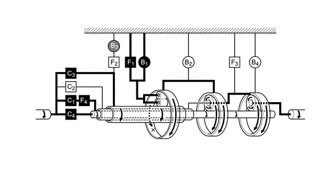
1st Gear (Shift Lever in D or M)
Text in Illustration 
Operates 
Operates (M Mode) Operating Condition of Friction Engagement Components and 1-way Clutch Gear Position C1
C2
C3
C4
B1
B2
B3
B4
F1
F2
F3
F4
Gear ratio 1st ○ - - (○) - - - (○) - - ○ ○ 3.538 Tech Tips
○: Operates
(○): Operates (M Mode)
-: Does not operate
-
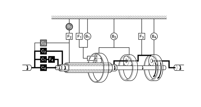
2nd Gear (Shift Lever in D or M)
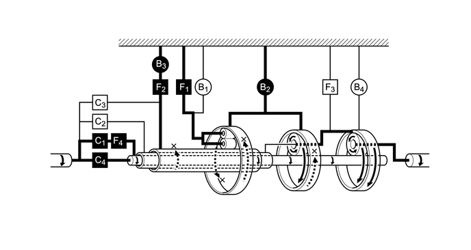
Text in Illustration Operates - - Operating Condition of Friction Engagement Components and 1-way Clutch Gear Position C1
C2
C3
C4
B1
B2
B3
B4
F1
F2
F3
F4
Gear ratio 2nd ○ - - ○ - ○ ○ - ○ ○ - ○ 2.060 Tech Tips
○: Operates
-: Does not operate
-
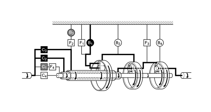
3rd Gear (Shift Lever in D or M)
Text in Illustration Operates 
Operates but is not related to power transmission Operating Condition of Friction Engagement Components and 1-way Clutch Gear Position C1
C2
C3
C4
B1
B2
B3
B4
F1
F2
F3
F4
Gear ratio 3rd ○ - ○ ○ ○ - ● - ○ - - ○ 1.404 Tech Tips
○: Operates
●: Operates but is not related to power transmission
-: Does not operate
-
4th Gear (Shift Lever in D or M)
Text in Illustration Operates Operates but is not related to power transmission Operating Condition of Friction Engagement Components and 1-way Clutch Gear Position C1
C2
C3
C4
B1
B2
B3
B4
F1
F2
F3
F4
Gear ratio 4th ○ ○ ● ○ - - ● - - - - ○ 1.000 Tech Tips
○: Operates
●: Operates but is not related to power transmission
-: Does not operate
-
5th Gear (Shift Lever in D or M)
Text in Illustration Operates Operates but is not related to power transmission Operating Condition of Friction Engagement Components and 1-way Clutch Gear Position C1
C2
C3
C4
B1
B2
B3
B4
F1
F2
F3
F4
Gear ratio 5th ● ○ ○ - ○ - ● - - - - - 0.713 Tech Tips
○: Operates
●: Operates but is not related to power transmission
-: Does not operate
-
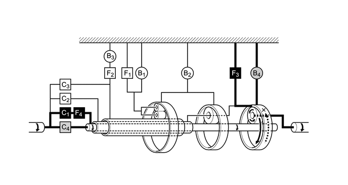
6th Gear (Shift Lever in D or M)
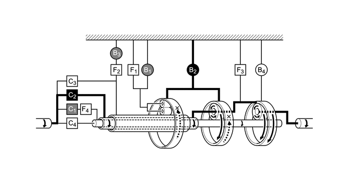
Text in Illustration Operates Operates but is not related to power transmission Operating Condition of Friction Engagement Components and 1-way Clutch Gear Position C1
C2
C3
C4
B1
B2
B3
B4
F1
F2
F3
F4
Gear ratio 6th ● ○ - - ● ○ ● - - - - - 0.582 Tech Tips
○: Operates
●: Operates but is not related to power transmission
-: Does not operate
-
Reverse Gear (Shift Lever in R)
Text in Illustration Operates - - Operating Condition of Friction Engagement Components and 1-way Clutch Gear Position C1
C2
C3
C4
B1
B2
B3
B4
F1
F2
F3
F4
Gear ratio Reverse - - ○ - ○ - - ○ ○ - - - 3.168 Tech Tips
○: Operates
-: Does not operate
-
-
-
FAIL-SAFE
-
This function minimizes the loss of operability when an abnormality occurs in a sensor or solenoid.For details, refer to the Repair Manual.
-
-
DIAGNOSIS
-
When the transmission control ECU assembly detects a malfunction, it makes a diagnosis and memorizes the failed section. Furthermore, the ECM illuminates or blinks the MIL in the combination meter assembly to inform the driver.
-
The transmission control ECU assembly will also store the Diagnostic Trouble Codes (DTCs) of the malfunctions.
-
The DTCs can be read by connecting an Global TechStream(GTS) to the DLC3.
-
For details, refer to the corresponding Repair Manual for this model.
-