FRONT PNEUMATIC CYLINDER(for 2WD) REMOVAL
CAUTION / NOTICE / HINT
The necessary procedures (adjustment, calibration, initialization, or registration) that must be performed after parts are removed, installed, or replaced during the front pneumatic cylinder removal/installation are shown below.
| Necessary Procedure After Parts Removed/Installed/Replaced | ||||||||||||||
|---|---|---|---|---|---|---|---|---|---|---|---|---|---|---|
|
Note
-
When the brake pedal is first depressed after replacing the brake pads or pushing back the disc brake piston, DTC C1341, C1342, C1343 and/or C1344 may be stored. As there is no malfunction, clear the DTCs. (w/o Vacuum Brake Booster)
-
While the battery is connected, even if the engine switch is off, the brake control system activates when the brake pedal is depressed or any door courtesy switch is turned on. Therefore, when servicing, do not depress the brake pedal or open/close the doors while the battery is connected. (w/o Vacuum Brake Booster)
-
Be sure to read the "PRECAUTION" thoroughly before servicing.
-
In order to prevent the battery from becoming fully depleted, connect the battery charger to the battery when turning the engine switch on (IG) to charge the battery.
-
Keep the power supply connected to prevent the GTS battery from becoming fully depleted.
Tech Tips
-
Use the same procedure for the RH and LH side.
-
The following procedure is for the LH side.
PROCEDURE
-
AIR SUSPENSION CONTROL PROHIBITED (WHEN REPLACING A FRONT PNEUMATIC CYLINDER)
Tech Tips
Check each part and system if an error is displayed for air movement pattern A.
-
Connect the GTS to the DLC3 with the engine switch off.
-
Turn the engine switch on (IG).
-
Turn the GTS on and enter the following menus: Chassis / Air suspension / Utility / Air Transfer Pattern A.
Chassis > Air suspension > UtilityTester Display Air Transfer Pattern A -
Perform vehicle height control prohibition and air movement according to the instructions on the GTS.
-
-
AIR SUSPENSION CONTROL PROHIBITED (WHEN REPLACING THE 2 FRONT PNEUMATIC CYLINDERS)
Tech Tips
Check each part and system if an error is displayed for air movement pattern B.
-
Connect the GTS to the DLC3 with the engine switch off.
-
Turn the engine switch on (IG).
-
Turn the GTS on and enter the following menus: Chassis / Air suspension / Utility / Air Transfer Pattern B.
Chassis > Air suspension > UtilityTester Display Air Transfer Pattern B -
Perform vehicle height control prohibition and air movement according to the instructions on the GTS.
-
-
DISCONNECT BRAKE BOOSTER PUMP CONNECTOR (w/o Vacuum Brake Booster)
-
REMOVE UPPER RADIATOR SUPPORT SEAL (for LH Side)
-
REMOVE RADIATOR COVER PLATE (for RH Side)
-
REMOVE FRONT WHEEL
-
REMOVE ABSORBER CONTROL WIRE LH
-
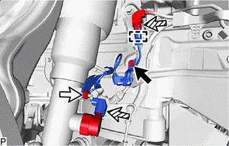

Bolt 
Nut 
Connector Remove the bolt and nut.
-
Disconnect the clamp, 2 connectors and remove the absorber control wire LH.
-
-
DISCONNECT FRONT STABILIZER LINK ASSEMBLY LH
-
DISCONNECT FRONT HEIGHT CONTROL SENSOR SUB-ASSEMBLY LH
-
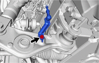
Remove the bolt and disconnect the front height control sensor sub-assembly LH.
-
-
DISCONNECT FRONT SKID CONTROL SENSOR WIRE LH
-
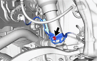
Remove the nut and disconnect the front skid control sensor wire LH.
-
-
DISCONNECT DISC BRAKE CYLINDER ASSEMBLY LH
-
DISCONNECT STEERING KNUCKLE ASSEMBLY LH
-
DISCONNECT NO.4 HEIGHT CONTROL TUBE
-
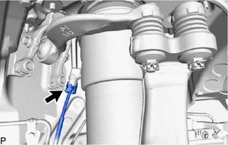
Disconnect the No. 4 height control tube from the front pneumatic cylinder with shock absorber assembly LH.
-
-
REMOVE FRONT SHOCK ABSORBER CAP LH
-
REMOVE FRONT PNEUMATIC CYLINDER WITH SHOCK ABSORBER ASSEMBLY LH
-
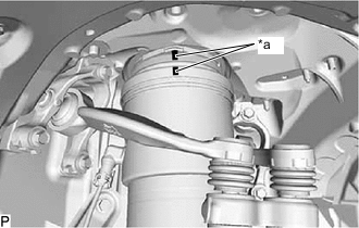
*a Matchmark When reusing the front pneumatic cylinder with shock absorber assembly LH:
-
Place matchmarks on the front suspension support assembly and pneumatic cylinder chamber.
-
-
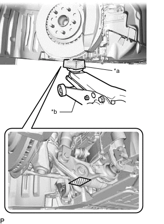
*a Wooden Block *b Jack Support the lower No. 2 suspension arm assembly LH using a jack and wooden block.
-
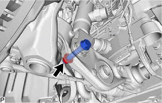
Remove the nut.
Note
-
Because the nut has its own stopper, do not turn the nut. Loosen the bolt with the nut secured.
-
Do not remove the bolt.
-
-
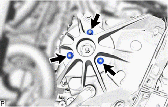
Remove the 3 nuts from the front pneumatic cylinder with shock absorber assembly LH (upper side).
-
Remove the bolt from the front pneumatic cylinder with shock absorber assembly LH (lower side).
-
Slowly lower the jack and remove the front pneumatic cylinder with shock absorber assembly LH.
-
When reusing the front pneumatic cylinder with shock absorber assembly LH:
-
Remove the No. 2 connector, plate and 2 O-rings.
-
-