ГОЛОВКА БЛОКА ЦИЛИНДРОВ ПОВТОРНАЯ СБОРКА

PROCEDURE
-
INSTALL SPARK PLUG TUBE
Tech Tips
When using a new cylinder head sub-assembly, the spark plug tubes must be replaced.
-
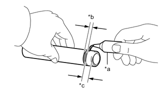
*a Adhesive *b Application Width *c Distance Apply adhesive to a new spark plug tube as shown in the illustration.
Adhesive Toyota Genuine Adhesive 1324, Three Bond 1324 or equivalent Standard Application Width 1.0 to 3.0 mm (0.0394 to 0.118 in.) Distance 1.0 to 7.0 mm (0.0394 to 0.276 in.) Note
-
Install the spark plug tube within 3 minutes of applying adhesive.
-
Be careful not to deform the spark plug tube.
-
Do not expose the spark plug tube to engine oil for at least 1 hour after installing it.
-
-
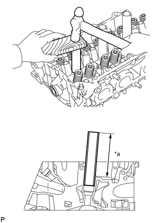
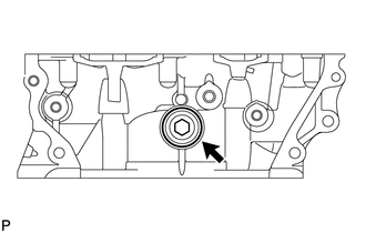
*a Protrusion Height Using a wooden block and hammer, tap in the spark plug tube to the specified protrusion height.
Standard Protrusion Height 112 mm (4.41 in.) Note
To avoid tapping in the spark plug tube too far, measure the protrusion height while tapping it.
-
-
INSTALL STUD BOLT
-
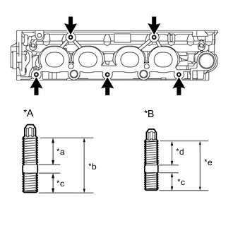
*A Type A *B Type B *a 18 mm (0.708 in.) *b 33 mm (1.30 in.) *c 13 mm (0.512 in.) *d 20 mm (0.787 in.) *e 35 mm (1.38 in.) Using an E7 or E8 "TORX" socket wrench, install the 5 stud bolts.
- Torque:
- 9.0 N*m { 92 kgf*cm, 80 in.*lbf }
-
-
INSTALL NO. 1 STRAIGHT SCREW PLUG
-
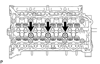
Using a 10 mm hexagon wrench, install 3 new gaskets and the 3 No. 1 straight screw plugs.
- Torque:
- 44 N*m { 449 kgf*cm, 32 ft.*lbf }
-
-
INSTALL NO. 2 STRAIGHT SCREW PLUG
-
Using a 14 mm hexagon wrench, install a new gasket and the No. 2 straight screw plug.
- Torque:
- 78 N*m { 795 kgf*cm, 58 ft.*lbf }
-
-
INSTALL VALVE SPRING SEAT
-
Install the valve spring seat to the cylinder head sub-assembly.
-
-
INSTALL VALVE STEM OIL SEAL
-
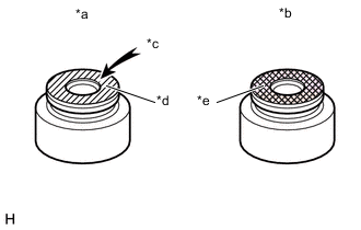
*a Intake Valve Stem Oil Seal *b Exhaust Valve Stem Oil Seal *c "NOK" Mark *d Gray *e Black Apply a light coat of engine oil to new valve stem oil seals.
Note
Make sure to install each valve stem oil seal to the correct side. Installing an intake valve stem oil seal to the exhaust side or installing an exhaust valve stem oil seal to the intake side can cause installation problems later.
Tech Tips
The intake valve stem oil seals are gray and the exhaust valve stem oil seals are black.
-
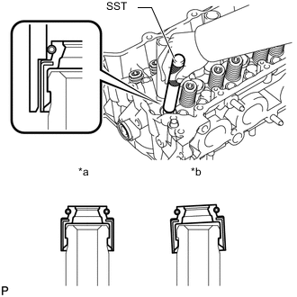
*a Correct *b Incorrect Using SST, push in the valve stem oil seal.
- SST
- 09201-41020
Note
Failure to use SST will cause the valve stem oil seals to be damaged or improperly seated.
-
-
INSTALL INTAKE VALVE
Tech Tips
Type A and Type B can be distinguished by the shape of the compression spring.
Type Compression Spring Shape A Straight B Tapered 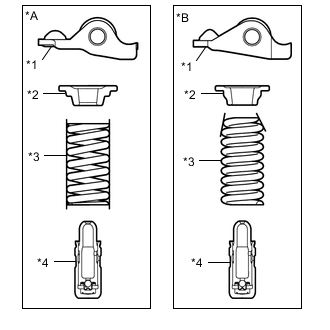
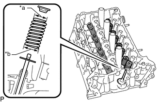
*A Type A *B Type B *1 No. 1 Valve Rocker Arm Sub-assembly *2 Valve Spring Retainer *3 Compression Spring *4 Valve Lash Adjuster Assembly
-
Type A:
-
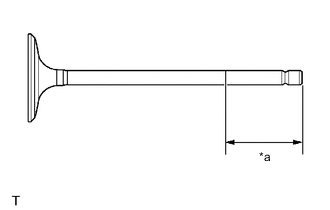
*a 30 mm (1.18 in.) or more Sufficiently apply engine oil to the tip area of the intake valve shown in the illustration.
-
Install the intake valve, compression spring and valve spring retainer to the cylinder head sub-assembly.
Note
Install the same parts in the same combination to their original locations.
-
Install the intake valve, compression spring and valve spring retainer to the cylinder head sub-assembly.
-
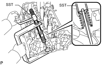
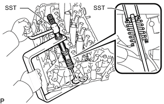
Using SST, compress the compression spring and install the valve spring retainer lock.
- SST
- 09202-70020 ( 09202-01010, 09202-01020, 09202-00010 )
-
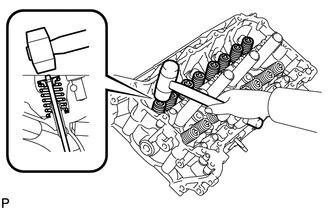
Using a plastic hammer, lightly tap the valve stem tip to ensure a proper fit.
Note
Be careful not to damage the valve spring retainer.
-
-
Type B:
-
*a 30 mm (1.18 in.) or more Sufficiently apply engine oil to the tip area of the intake valve shown in the illustration.
-
Install the intake valve, compression spring and valve spring retainer to the cylinder head sub-assembly.
Note
Install the same parts in the same combination to their original locations.
-
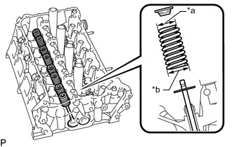
*a Narrow *b Wide Install the intake valve, compression spring and valve spring retainer to the cylinder head sub-assembly.
-
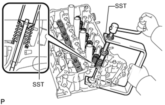
Using SST, compress the compression spring and install the valve spring retainer lock.
- SST
- 09202-70020
- 09202-00021
-
Using a plastic hammer, lightly tap the valve stem tip to ensure a proper fit.
Note
Be careful not to damage the valve spring retainer.
-
-
-
INSTALL EXHAUST VALVE
Tech Tips
Type A and Type B can be distinguished by the shape of the compression spring.
Type Compression Spring Shape A Straight B Tapered
*A Type A *B Type B *1 No. 1 Valve Rocker Arm Sub-assembly *2 Valve Spring Retainer *3 Compression Spring *4 Valve Lash Adjuster Assembly
-
Type A:
-
*a 30 mm (1.18 in.) or more Sufficiently apply engine oil to the tip area of the exhaust valve shown in the illustration.
-
Install the exhaust valve, compression spring and valve spring retainer to the cylinder head sub-assembly.
Note
Install the same parts in the same combination to their original locations.
-
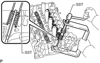
Using SST, compress the compression spring and install the valve spring retainer lock.
- SST
- 09202-70020 ( 09202-01010, 09202-01020 )
- 09202-00020
-
Using a plastic hammer, lightly tap the valve stem tip to ensure a proper fit.
Note
Be careful not to damage the valve spring retainer.
-
-
Type B:
-
*a 30 mm (1.18 in.) or more Sufficiently apply engine oil to the tip area of the exhaust valve shown in the illustration.
-
*a Narrow *b Wide Install the exhaust valve, compression spring and valve spring retainer to the cylinder head sub-assembly.
Note
Install the same parts in the same combination to their original locations.
-
Using SST, compress the compression spring and install the valve spring retainer lock.
- SST
- 09202-70020
- 09202-00021
-
Using a plastic hammer, lightly tap the valve stem tip to ensure a proper fit.
Note
Be careful not to damage the valve spring retainer.
-
-