AIR CONDITIONING SYSTEM(for Automatic Air Conditioning System), Diagnostic DTC:B1440/41, B1442/-41, B1446/E41
| DTC Code | DTC Name |
|---|---|
| B1440/41 | Open in Driver Side Air Mix Damper Position Sensor Circuit |
| B1442/-41 | Short in Driver Side Air Mix Damper Position Sensor Circuit |
| B1446/E41 | Driver Side Air Mix Damper Control Servomotor Circuit |
DESCRIPTION
This sensor detects the position of the air mix damper and sends appropriate signals to the A/C amplifier assembly.
The position sensor is built into the air mix control servo motor.
Tech Tips
Confirm that no mechanical problem is present because this diagnostic code can be output when either a damper link or the damper is mechanically locked.
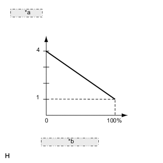
| *a | Voltage (V) |
| *b | Damper opening angle |
| DTC No. | DTC Detection Condition | Trouble Area |
|---|---|---|
| B1440/41 | Open in driver side air mix damper position sensor circuit |
|
| B1442/-41 | Short in driver side air mix damper position sensor circuit |
|
| B1446/E41 | Driver side air mix damper position sensor circuit |
|
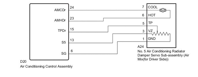
WIRING DIAGRAM
CAUTION / NOTICE / HINT
Note
This DTC is stored even for damper link and damper lock, etc. Prior to inspection, confirm that there are no parts with mechanical problems.
PROCEDURE
-
READ VALUE USING GTS
-
Connect the GTS to the DLC3.
-
Turn the ignition switch to ON.
-
Turn the GTS on.
-
Operate the driver side temperature adjustment switch.
-
Enter the following menus: Body Electrical / Air Conditioner / Data List.
-
Check the value(s) by referring to the table below.
Air Conditioner Tester Display Measurement Item/Range Normal Condition Diagnostic Note Air Mix Damper Position (D)
(A/M Damp Pos-D))
Driver side air mix damper position /
Min.: -32.68%, Max.: 133.33%
MAX COLD: 0%
MAX HOT: 110%
- Air Mix Damper Target (D)
(A/M Damp Targ-D)
Driver side air mix damper target position /
Min.: -32.68%, Max.: 133.33%
MAX COLD: 0%
MAX HOT: 110%
- OK The display is as specified in the normal condition column.
NG 
CHECK HARNESS AND CONNECTOR (NO. 5 AIR CONDITIONING RADIATOR DAMPER SERVO SUB-ASSEMBLY - AIR CONDITIONING CONTROL ASSEMBLY) Click here
OK 
-
-
CHECK FOR DTC
-
Clear the DTCs Click here.
-
Check the DTCs Click here.
OK DTC is not output.
OK 
END
NG
REPLACE AIR CONDITIONING CONTROL ASSEMBLY Click here
-
-
CHECK HARNESS AND CONNECTOR (NO. 5 AIR CONDITIONING RADIATOR DAMPER SERVO SUB-ASSEMBLY - AIR CONDITIONING CONTROL ASSEMBLY)
-
Disconnect the D20 air conditioning control assembly.
-
Disconnect the A24 No. 5 air conditioning radiator damper servo sub-assembly (air mix (for driver side)).
-
Measure the resistance according to the value(s) in the table below.
Standard Resistance Tester Connection Condition Specified Condition A24-1(GND) - D20-6(SG) Always Below 1 Ω A24-3(VZ) - D20-13 Always Below 1 Ω A24-5(TP) - D20-15(TPDr) Always Below 1 Ω A24-6(HOT) - D20-23(AMCDr) Always Below 1 Ω A24-7(COOL) - D20-24(AMHDr) Always Below 1 Ω A24-1(GND) - Body ground Always 10 kΩ or higher A24-3(VZ) - Body ground Always 10 kΩ or higher A24-5(TP) - Body ground Always 10 kΩ or higher A24-6(HOT) - Body ground Always 10 kΩ or higher A24-7(COOL) - Body ground Always 10 kΩ or higher
NG
REPAIR OR REPLACE HARNESS AND CONNECTOR
OK
-
-
INSPECT NO. 5 AIR CONDITIONING RADIATOR DAMPER SERVO SUB-ASSEMBLY
-
Remove the No. 5 air conditioning radiator damper servo sub-assembly (air mix (for driver side)) Click here.
-
Potentiometer circuit inspection
-
Measure the resistance according to the value(s) in the table below.
Standard resistance Tester Connection Condition Specified Condition A24-1(GND) - A24-3(VZ) Always 4.2 to 7.8 kΩ 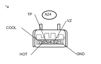
Text in Illustration *a Component without harness connected
(No. 5 air conditioning radiator damper servo sub-assembly)
-
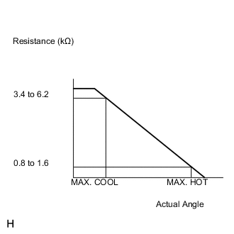
Measure the resistance according to the value(s) in the table below.
Standard resistance Tester Connection Condition Specified Condition A24-1(GND) - A24-5(TP) MAX. COOL position 3.4 to 6.2 kΩ A24-1(GND) - A24-5(TP) MAX. HOT position 0.8 to 1.6 kΩ 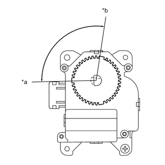
Text in Illustration *a MAX. COOL *b MAX. HOT -
As the arm of the air mix control servo motor moves from the COOL side to the HOT side, the resistance decreases gradually without interruption.
-
-
Motor circuit inspection
-
When the terminal 7(COOL) of the connector A24 is connected to the battery positive terminal, and terminal 6 (HOT) of the connector A24 is connected to the battery negative terminal, confirm that the arm smoothly rotates from HOT to COOL.
Tech Tips
Because the arm does not automatically stop at servo unit inspection, at inspection, turn off the power supply near COOL.
-
When the terminal 7 (HOT) of the connector A28 is connected to the battery positive terminal, and terminal 6 (COOL) of the connector A28 is connected to the battery negative terminal, confirm that the arm smoothly rotates from COOL to HOT.
Tech Tips
Because the arm does not automatically stop at servo unit inspection, at inspection, turn off the power supply near HOT.
-
OK
REPLACE AIR CONDITIONING CONTROL ASSEMBLY Click here
NG
REPLACE NO. 5 AIR CONDITIONING RADIATOR DAMPER SERVO SUB-ASSEMBLY Click here
-