DIFFERENTIAL SYSTEM (w/ Differential Lock) INSPECTION
-
INSPECT DIFFERENTIAL LOCK SYSTEM
-
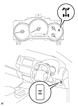
Inspect the indicator light.
-
Check that the indicator light lights up for approximately 1 second when the ignition switch is turned to ON.
-
-
Inspect the differential lock operation.
-
Jack up the vehicle and start the engine.
-
Shift the transfer shift lever to the L position.
-
When the differential lock control switch is set to the ON position, the indicator light turns on. Differential lock is applied to the rear wheel at this time.
Tech Tips
If the gears of the differential lock system are not meshed, the indicator light remains blinking, so rotate the tires to mesh the gears.
-
When the differential lock control switch is at the OFF position, the indicator light goes off. Differential lock is released for the rear wheel at this time.
-
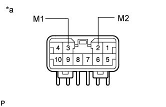
Text in Illustration *a ECU Side Check the voltage between the terminals of the four wheel drive control ECU when switching the differential control switch with the speedometer registering approximately 8 km/h (5 mph) or more.
Switch Position Terminal Specified Condition ON 3 (M1) to 2 (M2) 0.5 V or less (No change) -
Return the differential lock control switch to OFF.
-
Stop the engine and lower the vehicle.
-
-
-
CHECK WIRE HARNESS AND CONNECTOR
-
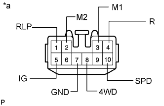
Text in Illustration *a Wire Harness Side Inspect the system circuit with the connector disconnected.
-
Disconnect the connector from the four wheel drive control ECU and inspect the connector on the wire harness side as shown in the table.
Standard Voltage Tester Connection Trouble Part Condition Specified Condition 3 (M1) - 2 (M2) Rear differential lock actuator - Less than 100 Ω 7 (GND) - Body ground Body ground - Below 1 Ω 10 (SPD) - Body ground Speed sensor Vehicle moves slowly 1 pulse generation per 40 cm (15.75 in.) 5 (IG) - Body ground Differential fuse Ignition switch ON 10 to 14 V 1 (RLP) - Body ground Rear differential lock indicator switch Ignition switch ON with indicator light ON About 0 V Ignition switch ON with indicator light OFF 10 to 14 V 8 (4WD) - Body ground L position switch Ignition switch ON with transfer shift lever not in L About 0 V Ignition switch ON with transfer shift lever in L 10 to 14 V 4 (R) - Body ground Differential lock control switch Ignition switch ON with differential lock control switch ON 10 to 14 V Ignition switch ON with differential lock control switch OFF About 0 V Tech Tips
If the result is not as specified, check and repair or replace the trouble part shown in the table above.
-
-
-
CHECK FOUR WHEEL DRIVE CONTROL ECU NO. 2
-
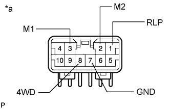
Text in Illustration *a ECU Side Inspect the system circuit with the connector connected.
-
Turn the ignition switch to ON.
-
Shift the transfer shift lever to the L position.
-
Using a voltmeter, measure the voltage when the differential lock control switch is in the position shown in the table.
Standard Voltage Tester Connection Switch Position Specified Condition 8 (4WD) - 7 (GND) - 0.5 V or less 1 (RLP) - 7 (GND) ON* 0.5 V or less 3 (M1) - 2 (M2) OFF → ON 0.5 V or less → 10 to 14 V (approx. 1 sec.) → 0.5 V or less 2 (M2) - 3 (M1) ON → OFF Tech Tips
*: The rear differential should be locked mechanically.
-
If the result is not as specified, replace the ECU.
-
-
Install the ECU.
-
-
-
INSPECT DIFFERENTIAL LOCK COMPONENTS
-
Inspect the relay operation.
-
Jack up the vehicle.
-
Use a heater main relay and connect it as shown below.
Note
Connect the terminals while being careful not to touch the neighboring terminals or metallic parts of the relay housing.
-
Rotate the tire and check that the differential lock has occurred.
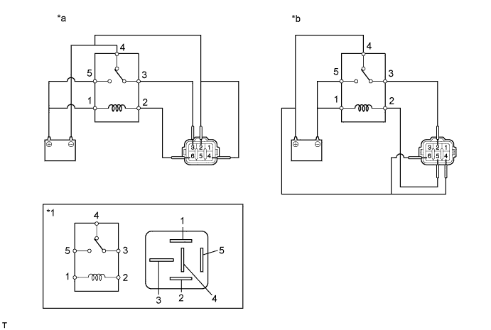
Text in Illustration *1 Heater Main Relay - - *a Free → Lock *b Lock → Free
-
If the operation is not as specified, replace the actuator.
-
-
-
-
INSPECT DIFFERENTIAL LOCK SWITCH
-
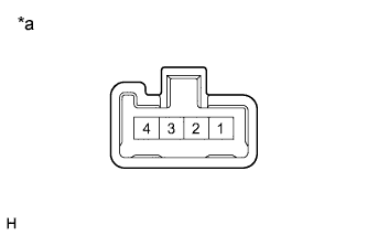
Text in Illustration *a Component without harness connected
(Differential Lock Switch)
Measure the resistance according to the value(s) in the table below.
Standard Resistance Tester Connection Switch Condition Specified Condition 3 - 4 OFF 10 kΩ or higher ON Below 1 Ω If the result is not as specified, replace the switch.
-
-
INSPECT NO. 4 TRANSFER INDICATOR SWITCH
-
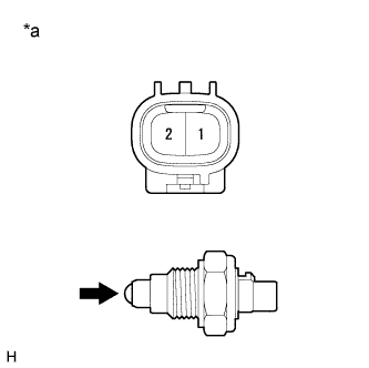
Text in Illustration *a Component without harness connected
(No. 4 Transfer Indicator Switch)
Measure the resistance according to the value(s) in the table below.
Standard Resistance Tester Connection Switch Condition Specified Condition 2 - 1 Pushed Below 1 Ω Not pushed 100 kΩ or higher If the result is not as specified, replace the No. 4 transfer indicator switch.
-